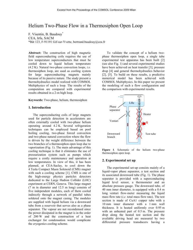
Excerpt from the Proceedings of the COMSOL Conference 2009 Milan Helium Two-Phase Flow in a Thermosiphon Open Loop F. Visentin, B. Baudouy* CEA, Irfu, SACM *Bât 123, F-91191 Gif-sur-Yvette, bertrand.baudouy@cea.fr Abstract: The construction of high magnetic field superconducting coils requires the use of low temperature superconductors that must be cooled down to liquid helium temperature (4.2 K). Natural two-phase convection loops, i.e. thermosiphon loop, are used as cooling system for large superconducting magnets mainly because of its passive nature. The study present a thermohydraulics model realized with COMSOL Multiphysics of such a loop. The results of the computation are compared with experimental results obtained in a 2-m high loop. To validate the concept of a helium twophase thermosiphon open loop, a single tube experimental test apparatus has been built [2] (see also Fig. 1) and several experimental studies have been achieved on heat transfer [3], pressure drop [4] and general thermohydraulics behavior [2], [5]. To build on these results, a predictive numerical model has been achieved with COMSOL Multiphysics. In this paper we present the modeling of such a flow configuration and the comparison with experimental results. Keywords: Two-phase, helium, thermosiphon 1. Introduction The superconducting coils of large magnets used for particle detection in accelerators are often externally cooled with two-phase helium operating around 4.2 K. Several refrigeration techniques can be employed based on pool boiling cooling, two-phase forced convection and two-phase natural convection where the flow is driven by the weight difference between the two branches of a thermosiphon open loop due to vaporization (Fig. 1). The main advantage of this cooling technique is that it eliminates the use of pressurization system such as pumps which require a costly maintenance and operation at low temperatures. In view of this, it has been planned, at CEA-Saclay, to cool down the 4 Tesla Compact Muon Solenoid (CMS) magnet with such a cooling scheme [1]. CMS is one of the high-energy physics particles detectors dedicated to the Large Hadron Collider (LHC) experiment at CERN, Geneva. This large magnet (7 m in diameter and 12.5 m long) consists of five independent modules, each of them cooled indirectly through a network of parallel tubes soldered onto the magnet casing. The modules are supplied with liquid helium via a downward tube from a reservoir that serves also as a phase separator. The vapour are not recondensed since the power dissipated in the magnet is in the order of 200 W and the construction of a heat exchanger for condensation would complicate the cryogenics cooling scheme. LHe Phase separator Heater Venturi Downward branch Test tube Figure 1. Schematic of the helium two-phase thermosiphon open loop. 2. Experimental set up The experimental set-up consists mainly of a liquid-vapor phase separator, a test section and its associated downward tube (Fig. 1). The phase separator is provided with a superconducting liquid level sensor, a thermometer and an absolute pressure gauge. The downward tube, of 40 mm inner diameter, is equipped with a 0.4 m long venturi flow-meter measuring the liquid mass flow rate (i.e. total mass flow rate). The test section is made of CuA1 copper tube with a 10 mm inner diameter with a 1 mm wall thickness. It is heated uniformly over 0.95 m with an unheated part of 0.5 m. The pressure drop along the heated test section and the available driving head are measured by two differential pressure transducers having a sensitivity of 2 Pa. The vapor mass flow rate mv is measured at room temperature by a gas flowmeter up to 4.2 g/s with a precision of 0.01 g/s. The exit vapor quality is obtained by computing x mv mt . The range of the experimental parameters covered by the present study is: 0≤ mt ≤12 g/s, 0≤x≤25% and 0≤q≤25 kW/m2. 3. Governing Equations dp dz where different for the downward and the test tube. θ is the inclination of the tube to the vertical. The subscript j stands for the branch, i.e. downward branch (d) or the heated tube (u). We will consider for each tube that the friction term is the contribution of the friction and a singular pressure term. For the downward branch it is dp dz 1.1 Homogeneous model Different models have been used to reproduce the pressure variation measurement obtained with such a loop [4]. The homogeneous model was found to have the best accuracy reproducing the experimental data and therefore was implemented in COMSOL Multiphysics. The homogeneous model considered the twophase mixture as a single fluid possessing mean fluid properties. The model is based on the following assumptions: both phases have the same velocity, u, the existence of a thermodynamic equilibrium and the use of a friction factor based on single phase friction factor. Our study concerns steady-state regime and we reduced the model to one dimension (z) for simplicity. The conservation of mass is written, d dz i du dz 0, 1 m x v 1 x (2) l where x is the vapor quality. ρv and ρl are respectively the vapor and the liquid densities. The conservation of momentum writes, dp dz iu du dz i g cos dp dz 0 , (3) f ,j f Dd f ,d d l ld u2 , 2 (4) where f is the friction factor defined by the Blasius correlation, 0.079 f Re j 0.25 . (5) The Reynolds number Re is always constructed with the liquid properties. ζj is the singular pressure drop coefficient taking account of any singularity like entrance, exit, bend and reduction encountered in the flow. lj is the length associated with the singularity. For the upward branch (heated tube), the friction term is dp dz (1) where the subscript i represents the phase state of the flow. In the liquid single phase flow the density is the liquid density ρl and in two-phase, the density is an average density ρm, defined as is the friction term and is f ,j where lo f Du f ,u u lu lo m u2 , 2 (6) is the two-phase multiplier defined by 1/ 4 l 1 x lo 1 1 x v l 1 . (7) v μv and μl are respectively the vapor and the liquid viscosities. The energy equation is described as 4 q Dj iu d hi dz u2 2 gz cos , (8) where q is the heat flux density, Dj is the diameter of the tube, hi the enthalpy. Since the height of the experimental loop is “small”, the variation of the thermophysical properties with the temperature or pressure is small. Therefore these properties are considered constant. For the same reason, the enthalpy definition was simplified. For single phase flow, the enthalpy is h=CpT, where Cp the specific heat. For the two-phase region the enthalpy is defined as CpT+xLv where Lv is the latent heat of vaporization. insert figure 2). Above point , the temperature of the mixture decreases following the saturation line since the pressure decreases. These conditions are implemented in the code. The straight section at the bottom of the loop is also modeled in vanishing the gravity term from equations (3) and (8). 1.2 Thermosiphon model 1.3 Use of COMSOL Multiphysics Additional conditions in relation with the flow configuration must be added to the equations system described in the previous paragraph. We have to consider the change of phases for the two branches and use thermodynamic properties. In the downward branch, the flow is single phase and the pressure and the temperature increase from the initial value at the free surface of the liquid (point ) to the bottom of the loop (point ) (see insert in figure 2). This branch is adiabatic and the liquid is sub-cooled. The upward branch is heated partially along its length from 0.07 m up to 0.95 m, and above it is adiabatic (the riser). In this branch, the flow is first in single phase until the temperature of the fluid reaches the saturation temperature at point . The saturation temperature is a function of the pressure and is implemented in the model. The PDE general form module was used to implement our equations system in COMSOL Multiphysics. To solve the equations system, we use the segregated mode where the equations system is separated into three groups. The first group concerns the resolution of the conservation of mass and momentum with u and p as variables. For the boundary conditions, the pressure is imposed at the entrance of the loop and a Neumann condition is set for the other boundary. For the velocity, only Neumann conditions are used since the loop “creates” the flow naturally; we should not impose any value. The second group concerns the resolution of the energy conservation equation and concern only the variable T. The temperature is imposed at the entrance of the loop (point ). Neumann boundary conditions are set for the other boundary. The third group concerns the vapor quality x. The quality is set to zero up the point that the temperature of the mixture reaches the saturation line (point ). In the two-phase region, from point to the exit of the loop, the energy equation is used to compute x. Liquid Vapor Two-phase flow Single phase flow Saturation line 3. Comparison with Experimental Results 3.1 Total Mass Flow Rate Figure 2. Flow configuration of the two-phase thermosiphon open loop and fluid temperature variation along the loop. Point is considered as the onset of nucleate boiling. Then the flow above is two-phase. In the - zone, the temperature of the fluid increases until it reaches the saturation line (see Figure 3 presents the comparison between experimental results of the total mass flow rate [6] and the results obtained with our model. The model reproduces with good accuracy the evolution of the total mass flow rate, mt , with the heat flux q. At low heat flux, the flow is dominated by the gravity term in the momentum equation whereas at higher heat flux the friction term increases explaining the slight decrease of the total mass flow rate. 3.2 Vapor Quality 5. Conclusions The vapor quality is reproduced with good accuracy up to 1500 W/m2 which is the value where film boiling appears in the tube [6]. The condition of thermodynamic equilibrium between the two phases does not stand anymore, explaining the failure of the homogeneous model to predict our measurements after 1500 W/m2. We manage to construct a numerical model with COMSOL Multiphysics to reproduce with good accuracy our experimental results on a helium two-phase thermosiphon open loop. The current model deals with a single tube flow and it is intended to extend this model to parallel multi-tubes to help in the design of large superconducting magnet cooling scheme. 0.012 6. References 0.010 mt (kg/s) 0.008 0.006 0.004 0.002 0.000 0 1000 2000 2 q (W/m ) Figure 3. Evolution of the total mass flow rate, mt, with the heat flux, q. Open squares are the experimental data [6] and the red solid line is the COMSOL Multiphysics computation (10 mm diameter tube). 0.40 0.35 0.30 x 0.25 0.20 0.15 1. Lottin, J.C. and F.-P. Juster, Liquid Helium Thermosiphon for the 4 Tesla CMS Solenoid. Adv. Cryo. Eng., 1998. 43: p. 1505-1511. 2. Baudouy, B., Heat and mass transfer in twophase He I thermosiphon flow. Adv. in Cryo. Eng., 2001. 47 B: p. 1514-1521. 3. Benkheira, L., B. Baudouy, and M. Souhar, Heat transfer characteristics of two-phase He I (4.2 K) thermosiphon flow. International Journal of Heat and Mass Transfer, 2007. 50(17-18): p. 3534-3544. 4. Baudouy, B. Pressure drop in two-phase He I natural circulation loop at low vapor quality. in International Cryogenic Engineering Conference proceedings. 2002. Grenoble, France. 5. Baudouy, B., Heat transfer near critical condition in two-phase He I thermosiphon flow at low vapor quality. Adv. in Cryo. Eng., 2003. 49: p. 1107-1114. 6. Benkheira, L., Contribution à l'étude des propriétés thermiques et hydrodynamiques d'un écoulement d'hélium normal (He I) diphasique en circulation naturelle pour le refroidissement des aimants supraconducteurs, in Mechanical Engineering. 2007, Institut Polytechnique de Lorraine: Nancy. 0.10 7. Acknowledgements 0.05 0.00 0 1000 2000 2 q (W/m ) Figure 4. Evolution of the vapor quality, x, with the heat flux, q. Open squares are the experimental data and the blue solid line is the COMSOL Multiphysics computation (10 mm diameter tube). This experimental work was supported by the CERN-CEA collaboration for the construction of the 4T CMS magnet.


