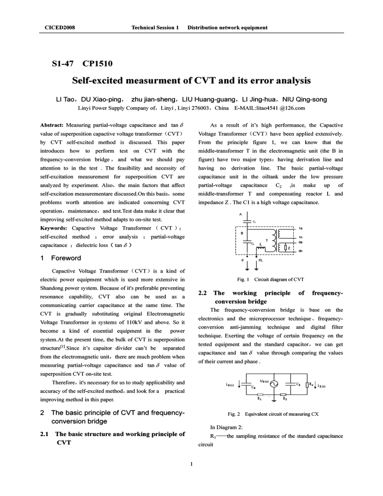
CICED2008 Technical Session 1 81-47 Distribution network equipment CP1510 Self-excited measurment of CVT and its error analysis LI Tao, DU Xiao-ping, zhu jian-sheng, LIU Huang-guang, LI Jing-hua, NIU Qing-song Linyi Power Supply Company of, Linyi, Linyi 276003, China E-MAIL:lita04541@126.com Abstract: Measuring partial-voltage capacitance and tan 8 As a result of it's high performance, the Capactive value of superposition capactive voltage transformer (CVT) Voltage Transformer (CVT) have been applied extensively. by CVT self-excited method is discussed. This paper From the principle figure I, we can know that the introduces the middle-transformer T in the electromagnetic unit (the B in frequency-conversion bridge, and what we should pay figure) have two major types: having derivation line and attention to in the test . The feasibility and necessity of having self-excitation measurement for superposition CVT are capacitance unit in the oiltank under the low pressure how to perform test on CVT with no derivation line. The basic analyzed by experiment. Also, the main factors that affect partial-voltage self-excitation measurementare discussed. On this basis, some middle-transformer T and compensating reactor Land problems worth attention are indicated concerning CVT impedance Z . The CI is a high voltage capacitance. capacitance C2 ,is partial-voltage make up of operation, maintenance, and test.Test data make it clear that improving self-excited method adapts to on-site test. :---- -----------0----- Keywords: Capactive Voltage Transformer (CVT); self-excited method ; error analysis ; 1 partial-voltage 1n Tid l__T~-~------Ltzj Foreword d Capactive Voltage Transformer (CVT) is a kind of electric power equipment which is used more extensive in Shandong power system. Because of it's preferable preventing resonance capability, CVT also can be used as a communicating carrier capacitance at the same time. The CVT is gradually substituting original Electromagnetic Voltage Transformer in systems of II0kV and above. So it become a kind of essential equipment in the power system.At the present time, the bulk of CVT is superposition structurel'ISince it's capaitor divider can't be separated from the electromagnetic unit, there are much problem when measuring partial-voltage capacitance and tan 8 value of 1a 1 1 I capacitance ; dielectric loss (tan 8 ) 1 B I : 1 I" d: Fig. 1 Circuit diagram ofCVT 2.2 The working principle conversion bridge The frequency-conversion bridge of frequency- is base on the electronics and the microprocessor technique" frequencyconversion anti-jamming technique and digital filter technique. Exerting the voltage of certain frequency on the tested equipment and the standard capacitor, we can get capacitance and tan 8 value through comparing the values of their current and phase. superposition CVT on-site test. x.I . Therefore, it's necessary for us to study applicability and accuracy of the self-excited method, and look for a R practical 1 XCt ) improving method in this paper. 2 The basic principle of CVT and frequencyconversion bridge 2.1 The basic structure and working principle of CVT Fig. 2 Equivalent circuit of measuring CX In Diagram 2: Rt-----the sampling resistance of the standard capacitance circuit CICED2008 Technical Session 1 Distribution network equipment R2 --the tested capacitance circuit When we test by the self-excited method, CVT's CN--the Equivalent capacitance of standard capacitor middle-transformer is acted as a experiment transformer. The Rx--the equivalent resistance exerted voltage on its secondary coil can arouse magnetizing Cx--the equivalent capacitanceof the tested equipment. Through carrying on an analysis and calculation With the u Rl(t) and the u R2(f) , we can figure out the phase difference Sx between the time, we can and the iN(t) iX(f). iX(f) and capactive current on primary winding which can be used as power supply to measure the value of capacitance C2 and C I and tan 0 . At the same work out the dielectric loss value tan Ox resistance current current .At the same time , the high voltage can be induced iX(f)C 3.1 ~ of the Measuring the value of capacitance C. and tant5. 3.1.1 tested equipment. As known from Diagram 2: Measuring the value of C. and tand, by self-excited method Since the experiment voltage can't be exerted on B terminal directly, the testing voltage can be rised by (1) middle-transformer of the electromagnetic unit. It's very easy ·2 fil" U R2(t) • lX(t)=--~-J 1i '--'xus R2 From the formula CX (1)~ () us(t). • (2) t +--=lx(t)C+lX(f)R Rx to measure C I of CVT by self-excited method with the frequency-conversion bridge .The A point connects signal (2) .we can know that: = iX(t)C . crN rrr terminal. The experiment voltage of C I can be exerted indirectly on the <i terminal and the high-voltage terminal of (3) =m~N standard capacitor (C N) .As known from the figure 3, we can IN(t) iX(t)C m=-- see the equivalent circuit of measuring C I and tand1 value by (4) self-excited method. iN(f) In the formula: j---plural factor. It means that the phase difference between current and voltage is plus 90 0; f---the output frequency of the frequency-conversion bridge; m---the ratio of the capactive current in tested equipment to the current in the standard capacitance circuit Fig.3 From Diagram 2 , we can know the dielectric loss value ofCX. Equivalent circuit of measuring Cl 3.1.2 The error analysis of measuring Cl and tanol value by self-excited method (5) From figure 3 .we can know that the value of 2.3 capacitance C2 and the insulation resistance Measuring the CVT by self-excited method The frequency-conversion bridge has been terminal will directly have an influence on the measure used results. extensively , because it has a good ability to limit primary voltage ( Ro ) of <i (1) In the vectorgraph 4(a), the dielectric loss angle of and secondary voltage of the CVT. When measuring C1 is equivalent to the phase difference between the current the CVT by the frequency-conversion bridg with self-excited IN and leI [3] without taking the influence of the capacitance method, C2 and the <i terminal into account. it can effectively avoid resonance. Because the capacitance C2 and C I in the superposition CVT are connected for a integral, (2) In the vectorgraph 4(b) , without calculating the measuring the capacitance and influence of the capacitance C2 and the <i terminal, tan 0 value of capacitance C2 and C I with self-excited see the formula we can ( 6) and (7): method is recommended in the specification'f . (6) Through correcting the error of test result according to the practice, the testing result can reflect their actual value of (7) capacitance and tan 0 more accurately.Therefore .we also can give an accurate judgment to the CVT's quality. In the formula: 2 CICED2008 Technical Session 1 Distribution network equipment The subscript p---the actual value testing precision of measuring instrument through distributed The subscript m---the measured value capacitance. It will make the testing value more bigger than Because of the influence of the C2, C1p<C 1m, the actual value. iiClp>iiClm. When C2»CN, the influence can.be ignored. l (3) When we calculate the ii terminal influences and ignore the taniic2' we can see the formula (8) and (9) from the vectorgraph 4( c): CI P ~ tan 0CIP Cl m • C2 (8) (C 2 + CNtan a) ~ tan 0Clm - 1 ( m R g(C2 + CN ) Fig. 5 Equivalent circuit of measuring C2 (10) m R g(C2 + CN ) The tanu is 9) 3.3 Other error analysis and attentions of self-excited method the ratio of the resistance current flowing through the ii terminal to the capacitive current of standard capacitor CN' (1) The voltage of electromagnetic unit When the ii terminal has fault insulation, the interference source will disturb testing accuracy of measuring measured value of C 1 will be bigger more than the actual instrument through ii terminal and distributed capacitance. It value. Because of the leakage resistance Rii, the voltage phase will make the measured value bigger more than actual of ii terminal will lead the testing power supplies phase. value[4l. As a result, the current phase of standard capacitor (CN) will be lead. The measured dielectric loss value of C 1 will be (2) According to the formula ZL=l/ro(C1+C2), ZL includes compensating-reactor's bigger more than the actual value. From the formula 10, we transformer's drain can see the increased value of the dielectric loss value. 3.2 middle-transformer when measuring C2. Therefore, the measuring voltage can't be exerted too high. Moreover, the capacity of secondary winding in CVT is not high, generally not more than 200VA. Owing to the high magnetizing voltageof secondary winding, it causes testing ( c ) calculating R 0 instrument protection to be acted or testing precision to Vectorgraph consideing C2 and R 8 bedisturbed. For example , the frequency-conversion bridge that we Measuring the value of C2 and tano2 by self-excited method use commonly is applied to that the testing high voltage is less than 4 kV . At the same time ,low-voltage magnetizing From figure 5 .we can see that experiment voltage is current is not allowed exceeding 30A. It is worry about that exerted on B terminal indirectly through middle-transformer the high voltage of electromagnetic unit. Since C1is in series with CN, it will (3) Measuring superposition capactive voltage transformer to its small influence, we can ignore it.The testing accuracy ( CVT) should be influenced by electromagnetic unit in a similar way 500-1000 V in 220 kV equipment area, As a result, the testing connected with the ii terminal on electromagnetic unit . The precision should be disturbed. connecting wire is so nearly with adjustive winding of capacitance. The voltage as to bring of adjustive some 4 distributed winding by self-excited method on site,We usually adopt the way of part blackout. The induced electricity can reach of positive connection. The low-voltage terminal of C2 is reactor and magnetizing current will bring experiment instrument to fault. influence the dielectric loss of branch circuit with CN. Owing compensating measuring C2, C2 is voltage is smaller than the voltage directly exerted on " Fig. 4 reactancell.When close to inductance ZL. Therefore the exerted secondary 11"" ( b) calculating C 2 reactance and middle- in series with ZL .At the same time , the capacitance ZC2 is ,, ,,, ,, ,,, ,, ,, ,, (a) ideal state as an within Conclusions We can arrive at a conclusion that test results of compensating reactor as a interference source will influence 3 CICED2008 Technical Session 1 Distribution network equipment partial-voltage capacitance and tan 8 value of the CVT by [3] Huang Tao, Liu Van, Li Guowei. "The Use of the self-excited method should be proofread. On this basis, the Frequency-Conversion Bridge in Test of the Capacitor test results can reflect the true device status. Test data make it Voltage Transformer without Disconnecting the Wire". clear that improving self-excited method adapts to on-site High Voltage Engineering, Vol 56, No.7, pp. 32-36, test. July. 2004. [4] Liang Zi-meng,Tan Van-mingo "tanbTest and Analysis References for CVT's EM Unit".High Voltage Engineering, Vol 72, [1] No.8, pp. 36-41, August. 2006. Jin Xu-dong, Jing Ke-yu. "Self-excited Method for Superposition CVT". Jiangsu Electrical Engineering, [2] [5] Zhang Ren-yu, Chen Chang-yu, Wang Li-chang. The Vol 26, No. 11, pp. 19-22, November. 2005. high electric voltage experiments technique, Qing Hua Chen Huan-gang. The electric power equipments university publishing company, Bei jing,2003. prevention experiments technique, Chinese science technique publishing method and diagnosis company, Beijing,2001. 4


