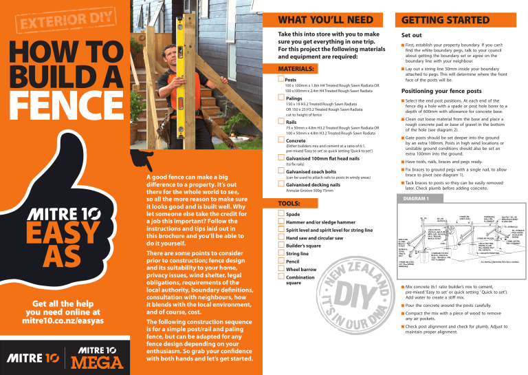
HOW TO BUILD A WHAT YOU’LL NEED GETTING STARTED Take this into store with you to make sure you get everything in one trip. For this project the following materials and equipment are required: Set out MATERIALS: P osts 00 x 100mm x 1.8m H4 Treated Rough Sawn Radiata OR 1 FENCE 100 x100mm x 2.4m H4 Treated Rough Sawn Radiata Palings 150 x 19 H3.2 Treated Rough Sawn Radiata OR 150 x 25 H3.2 Treated Rough Sawn Radiata cut to height of fence Rails 75 x 50mm x 4.8m H3.2 Treated Rough Sawn Radiata OR 100 x 50mm x 4.8m H3.2 Treated Rough Sawn Radiata Concrete (Either builders mix and cement at a ratio of 6:1, pre-mixed ‘Easy to set’ or quick setting ‘Quick to set’) Galvanised 100mm flat head nails (to fix rails) A good fence can make a big difference to a property. It’s out there for the whole world to see, so all the more reason to make sure it looks good and is built well. Why let someone else take the credit for a job this important? Follow the instructions and tips laid out in this brochure and you’ll be able to do it yourself. Get all the help you need online at mitre10.co.nz/easyas There are some points to consider prior to construction; fence design and its suitability to your home, privacy issues, wind shelter, legal obligations, requirements of the local authority, boundary definitions, consultation with neighbours, how it blends with the local environment, and of course, cost. The following construction sequence is for a simple post/rail and paling fence, but can be adapted for any fence design depending on your enthusiasm. So grab your confidence with both hands and let’s get started. Galvanised coach bolts (can be used to attach rails to posts in windy areas) Galvanised decking nails Annular Groove 500g 75mm TOOLS: First, establish your property boundary. If you can’t find the white boundary pegs, talk to your council about getting the boundary set or agree on the boundary line with your neighbour. Lay out a string line 50mm inside your boundary attached to pegs. This will determine where the front face of the posts will be. Positioning your fence posts Select the end post positions. At each end of the fence dig a hole with a spade or post hole borer to a depth of 600mm with allowance for concrete base. Clean out loose material from the base and place a rough concrete pad or base of gravel in the bottom of the hole (see diagram 2). Gate posts should be set deeper into the ground by an extra 100mm. Posts in high wind locations or unstable ground conditions should also be set an extra 100mm into the ground. Have tools, nails, braces and pegs ready. Fix braces to ground pegs with a single nail, to allow brace to pivot (see diagram 1). T ack braces to posts so they can be easily removed later. Check plumb before adding concrete. DIAGRAM 1 Spade Hammer and/or sledge hammer Spirit level and spirit level for string line Hand saw and circular saw Builder’s square String line Pencil Wheel barrow Combination square Mix concrete (6:1 ratio builder’s mix to cement, pre-mixed ‘Easy to set’ or quick setting ‘ Quick to set’). Add water to create a stiff mix. Pour the concrete around the posts carefully. Compact the mix with a piece of wood to remove any air pockets. Check post alignment and check for plumb. Adjust to maintain proper alignment. Set a string line at the top of the two end posts. This can be used as a guide to set posts at the correct height. Alternatively, they can be cut to height later. GETTING IT DONE E qually spread the intermediate posts along the string line. Posts should be a maximum of 2.3m apart, measured between centres (see diagram 1). Fixing the rails race posts using temporary rails. Check alignment B and vertical level on two adjacent faces using a spirit level (see diagram 2). Mix concrete or bags of quick drying cement and pour carefully around posts. Post alignment and plumb can be adjusted up to 5 minutes after concrete has been poured. However, if using quick setting ‘Quick to set’, you won’t be able to do any adjusting. DIAGRAM 2 Leave concrete to set for two days before fixing rails. Two rails are sufficient for fences up to 1200mm high. Use three rails for fence heights above 1200mm high. Use 100 x 50mm H3.2 treated rails. For smaller spans use 75 x 50mm H3.2 treated rails Rails can be fixed either between the posts (see diagram 4), or to the face of the post (see diagram 5), depending on fence style. STAY SAFE: The use of power tools makes the completion of projects much easier, but appropriate safety equipment when using power tools is highly recommended. Ear protection, eye wear and sturdy footwear should be considered the minimum requirement when using power tools and always use a residual current device when using electric power tools. Check alignment with string line and ensure the rails are square (see diagram 5). For between post rails (rails should be measured at ground level, squared and cut to length) fix to posts with three galvanised flat head nails 100mm long (see diagram 4). For face fixed rails (select a length of rail that can span three posts) fix with two galvanised flat head nails (see diagram 5). Remember measure twice, cut once. DIAGRAM 5 DIAGRAM 3 Palings DIAGRAM 4 Set string line at the height of the top of the palings. This can be done by fixing the first and last paling temporarily at the proper height and then setting the string line between them. Use a spirit level to regularly check that palings are plumb. Butt palings together as there will be shrinkage. Fix with galvanised flat head nails that are three times as long as paling thickness (see diagram 6). If the paling thickness is 25mm, use a minimum 75mm nail. If the paling is 19mm, use a minimum 60mm nail. If you want spaces between your palings, cut a block to size, then use this as a spacer between the palings (top and bottom) as you nail them in place. DIAGRAM 6 Limitation of Liability This project planner has been produced to provide basic information and our experienced staff are available to answer any questions you may have. Because this planner is general in nature, neither your Mitre 10 supplier nor thier staff are responsible for the application of these design principles in any particular case, as the contents of this brochure may need to be modified for the particular site and circumstances. Mitre 10 is not responsible for the quality of work carried out on the goods by the consumer and is not responsible for the design or construction of any structure in which the goods are incorporated. Where applicable consumers should ensure that they comply with The New Zealand Building Code and/or Local Body Bylaws in respect of any such structures. Consumers are advised to call a qualified tradesman such as a builder, electrician or plumber where expert services are required. Mitre 10 will not be liable for any consequential loss howsoever arising from the use of goods sold, nor for any loss caused by defective or inadequate structures in which goods are incorporated. For more Easy As to Guides visit mitre10.co.nz


