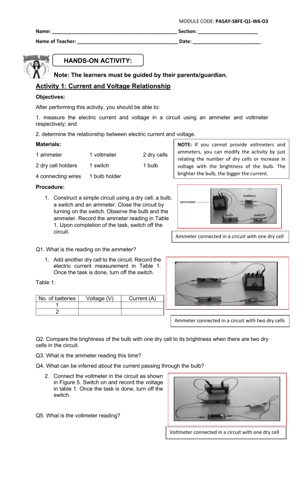
MODULE CODE: PASAY-S8FE-Q1-W6-D3 Name: ______________________________________________ Section: ______________________ Name of Teacher: _____________________________________ Date: _________________________ HANDS-ON ACTIVITY: Note: The learners must be guided by their parents/guardian. Activity 1: Current and Voltage Relationship Objectives: After performing this activity, you should be able to: 1. measure the electric current and voltage in a circuit using an ammeter and voltmeter respectively; and 2. determine the relationship between electric current and voltage. NOTE: If you cannot provide voltmeters and ammeters, you can modify the activity by just relating the number of dry cells or increase in voltage with the brightness of the bulb. The brighter the bulb, the bigger the current. Materials: 1 ammeter 1 voltmeter 2 dry cells 2 dry cell holders 1 switch 1 bulb 4 connecting wires 1 bulb holder Procedure: 1. Construct a simple circuit using a dry cell, a bulb, a switch and an ammeter. Close the circuit by turning on the switch. Observe the bulb and the ammeter. Record the ammeter reading in Table 1. Upon completion of the task, switch off the circuit. Ammeter connected in a circuit with one dry cell Q1. What is the reading on the ammeter? 1. Add another dry cell to the circuit. Record the electric current measurement in Table 1. Once the task is done, turn off the switch. Table 1: No. of batteries 1 2 Voltage (V) Current (A) Ammeter connected in a circuit with two dry cells Q2. Compare the brightness of the bulb with one dry cell to its brightness when there are two dry cells in the circuit. Q3. What is the ammeter reading this time? Q4. What can be inferred about the current passing through the bulb? 2. Connect the voltmeter in the circuit as shown in Figure 5. Switch on and record the voltage in table 1. Once the task is done, turn off the switch. Q5. What is the voltmeter reading? Voltmeter connected in a circuit with one dry cell MODULE CODE: PASAY-S8FE-Q1-W6-D3 Name: ______________________________________________ Section: ______________________ Name of Teacher: _____________________________________ Date: _________________________ 3. Add another dry cell to the circuit. Record the voltmeter reading in Table 1. Observe the brightness of the bulb. Once the task is done, turn off the switch. Q6. Describe the brightness of the bulb. Ammeter connected in a circuit with one dry cell Q7. What is the voltmeter reading this time? Q8. What can be inferred about the voltage across the bulb? Q9. Refer to Table 1, how are voltage and current related? Activity 2: Current and Resistance Relationship Objective: To determine the relationship between electric current and resistance. Materials: 1 ammeter holders 2 dry cells 2 dry cell 3 bulb holders 1 switch 4 connecting wires 3 flashlight bulbs NOTE: If you cannot provide voltmeters and ammeters, you can modify the activity by just relating the number of dry cells or increase in voltage with the brightness of the bulb. The brighter the bulb, the bigger the current. Procedure: 1. Construct a simple circuit using one bulb, 2 dry cells and an ammeter as shown in Figure 7. Record the electric current measurement in Table 2. Once the task is done, turn off the switch. 2. To increase the resistance, add another bulb in the circuit. Connect the ammeter and record the electric current measurement in Table 2. Once the task is done, turn off the switch. Ammeter connected in a circuit with one bulb and two dry cells cell Ammeter connected in a circuit with two bulbs and two dry cells 3. To further increase the resistance, add another bulb in the circuit. Connect the ammeter and record the electric current measurement in Table 2. Once the task is done, turn off the switch. Table 2: No. of bulbs 1 2 3 Current (A) Ammeter connected in a circuit with three bulbs and two dry cells MODULE CODE: PASAY-S8FE-Q1-W6-D3 Name: ______________________________________________ Section: ______________________ Name of Teacher: _____________________________________ Date: _________________________ Q10. Based on Table 2, what happens to the current in the circuit as the resistance increases (increasing of bulbs)? 4. Connect the ammeter at different points around the circuit shown in Figure 10. Make sure that the positive terminal of the ammeter is connected to the positive terminal of the dry cell while the negative terminal is connected to the negative terminal of the dry cell. Once the task is done, turn off the switch. Ammeter connected between two bulbs in a circuit Q11. Compare the current at different points in the circuit. Q12. What can you infer about the current through the circuit?


