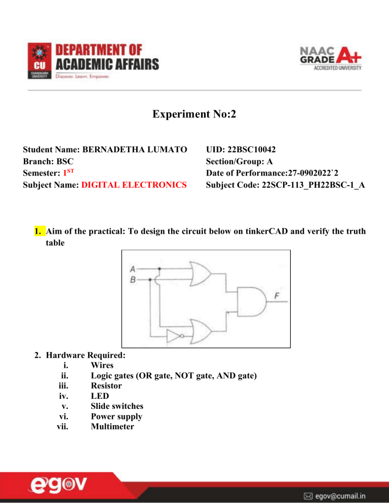
Experiment No:2 Student Name: BERNADETHA LUMATO Branch: BSC Semester: 1ST Subject Name: DIGITAL ELECTRONICS UID: 22BSC10042 Section/Group: A Date of Performance:27-0902022`2 Subject Code: 22SCP-113_PH22BSC-1_A 1. Aim of the practical: To design the circuit below on tinkerCAD and verify the truth table 2. Hardware Required: i. Wires ii. Logic gates (OR gate, NOT gate, AND gate) iii. Resistor iv. LED v. Slide switches vi. Power supply vii. Multimeter 3. Steps for experiment/ Theory: Open tinkerCAD Create a new workspace Input the breadboard Input the power supply Connect the positive to the positive part of breadboard and the negative likewise Connect the breadboard positives and negatives to each other Input the multimeter Connect the positive and negative of the multimeter with the positive and negative of the breadboard to check whether the breadboard is connected properly by starting the simulation Input two slide switches Connect the common terminal to the ground Input two resistors and connect them to the positive on one side and the first terminals of the slide switches respectfully Input the inverting (NOT) gate, the OR (7432 IC), the AND (7408 IC) Connect the inputs of each gate accordingly Input the LED and another resistor Connect one part of the resistor to the ground and the other to the cathode of the LED Connect the final output of the circuit to the anode and start the simulation, switching the switches on and off for different outputs. 4. Observations: When both switches are on the LED will light up When the first switch is on and the other off the LED will light up When the first switch is off and the second switch is on the LED does not light When both switches are off the LED does not light 5. Calculations: A 0 0 1 1 B 0 1 0 1 F= C*D = (A+B’)*(A+B) =A+(B’ * B) =A+0 =A THEREFORE; C A + B’ 1 0 1 1 D A+B 0 1 1 1 F=A F C*D 0 0 1 1 6. Output : 7. Learning outcomes (What I have learnt): 1.better use of the tinkerCAD software 2.better understanding of the use of the logic gates 3.better knowledge on designing circuits using tinkerCAD 4.How different components work differently for different circuits and circuit arrangements 5.how to design circuits with multiple gates.


