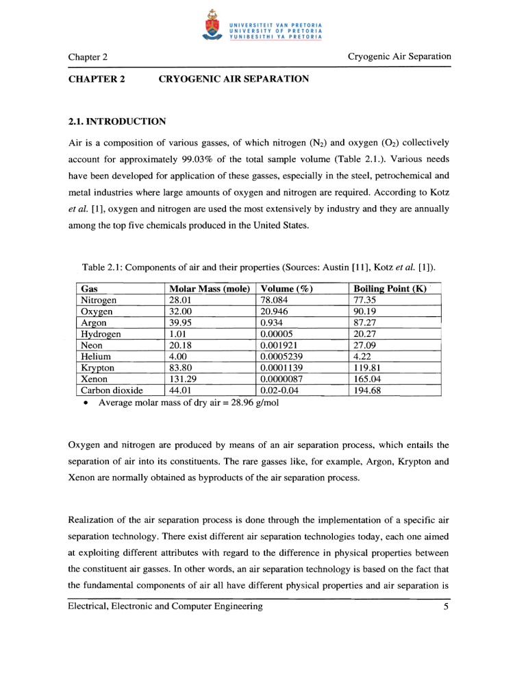
Cryogenic Air Separation Chapter 2 CHAPTER 2 CRYOGENIC AIR SEPARATION 2.1. INTRODUCTION Air is a composition of various gasses, of which nitrogen (N2) and oxygen (02) collectively account for approximately 99.03% of the total sample volume (Table 2.1.). Various needs have been developed for application of these gasses, especially in the steel, petrochemical and metal industries where large amounts of oxygen and nitrogen are required. According to Kotz et ai. [1], oxygen and nitrogen are used the most extensively by industry and they are annually among the top five chemicals produced in the United States. Table 2.1: Components of air and their properties (Sources: Austin [11], Kotz et ai. [1]). Molar Mass (mole) Volume (%) Gas Nitrogen 28.01 78.084 Oxygen 32.00 20.946 Argon 39.95 0.934 Hydrogen 1.01 0.00005 Neon 20.18 0.001921 Helium 4.00 0.0005239 Krypton 83.80 0.0001139 Xenon 131.29 0.0000087 Carbon dioxide 44.01 0.02-0.04 • Average molar mass of dry air =28.96 g/mol Boiling Point (K) . 77.35 90.19 87.27 20.27 27.09 4.22 119.81 165.04 194.68 Oxygen and nitrogen are produced by means of an air separation process, which entails the separation of air into its constituents. The rare gasses like, for example, Argon, Krypton and Xenon are normally obtained as byproducts of the air separation process. Realization of the air separation process is done through the implementation of a specific air separation technology. There exist different air separation technologies today, each one aimed at exploiting different attributes with regard to the difference in physical properties between the constituent air gasses. In other words, an air separation technology is based on the fact that the fundamental components of air all have different physical properties and air separation is Electrical, Electronic and Computer Engineering 5 Cryogenic Air Separation Chapter 2 therefore realized through, for example, distinguishing between molecule sizes, distinguishing between difference in diffusion rates through certain materials, adsorption preference special materials have towards certain gasses of the atmosphere and difference in boiling temperatures. Some of the technologies being used today include adsorption, chemical processes, polymeric membranes, ion transport membrane (ITM) and cryogenic. Table 2.2 compares the different air separation technologies to each other in terms of technology status, byproduct capability, product purity limit and plant startup time. As can be seen from the table, cryogenic air separation technology is in a mature stage of its life cycle, consequently making it the only feasible means currently available for mass production of air products such as oxygen and nitrogen. Table 2.2: Comparison of air separation technologies (Smith et ai. [2]). Process Adsorption Chemical Cryogenic Membrane ITM Status Semi -mature developing mature Semi-mature developing Byproduct capability Poor Poor Excellent Poor Poor Purity limit Start-up time (vol. %) minutes 93-95 >99 hours >99 hours 40 minutes >99 hours The sections that follow will be dedicated to cryogenic air separation technology. 2.2. PROCESS DESCRIPTION Cryogenic air separation technology is based on the fact that the different constituent gasses of air all have different boiling points and by manipulating the immediate environment in terms of temperature and pressure, the air can be separated into its components. Various processes are needed in a cryogenic air separation plant, of which the fundamental ones are: air compression, air purification, heat exchanging, distillation and product Electrical, Electronic and Computer Engineering 6 Cryogenic Air Separation Chapter 2 compression (figure 2.1). Air Product compression compression Product delivery I Air purification - Heat Distillation exchange Figure 2.1: Processes involved in cryogenic air separation. Each process of figure 2.1 has a certain function and this function is performed by means of relevant equipment; Table 2.3 lists the equipment type utiHzed in each of the required processes as well as their respective main functions. Table 2.3: A description on the function of each process and the equipment used for the implementation thereof. Process Air compression Air purification Heat exchanging Distillation Product compression Function Pressurize air feed lines in order to achieve required production Purifying the air by removing water and CO2 Cooling of incoming air feed by means of cold recovery from exiting products Partial separation of air into its constituents Pressurize outgoing product feed in to meet user requirement Electrical, Electronic and Computer Engineering Equipment type ! Compressor I Reversible exchangers/sieve adsorbers Heat exchanger Distillation columns Compressor 7 Chapter 2 Cryogenic Air Separation In figure 2.1, incoming air is pressurized by the air compressors and enters the process with a certain flow-rate, as determined by the demand of air product at the output of the plant. The air pre-treatment section removes impurities like water, carbon dioxide and hydrocarbons and is necessary because it prohibits vapour condensation, liquid water solidification and gaseous CO2 condensation from occurring within the heat-exchanger, thus ensuring continuous operation of a train. In order to obtain the required conditions for air distillation, the air first needs to be cooled down and this is done by means of heat exchanging between the air and outgoing product streams. The distillation process is at the heart of the overall process; this process performs the actual separation of air into its constituents. These air products are produced with a certain purity, which is defined as the ratio of the quantity of 100% pure air product to the quantity of total of air product at the output. The outputs from the distillation process are fed back through the heat exchanger in order to realize the cold recovery process that is needed for the cooling of the incoming air feed lines. The main air product is at low pressure when exiting the distillation process and is, for this reason, usually compressed to the client's pressure specification prior to delivery. The system, incorporating these processes, is referred to as an oxygen or nitrogen train, whatever the main product may be. A number of such trains are usually cascaded in order to produce a high-tonnage air product output and is then collectively referred to as an oxygen or nitrogen plant. The capacity, of cryogenic air separation trains, is expressed in tons per day (tpel) of main Electrical, Electronic and Computer Engineering 8 Cryogenic Air Separation Chapter 2 product output. The flow of air products is usually quantified in terms of normal-cubic meter per hour (Nm 31h), which is defined as the flow at 1.013 absolute bar and DoC. This is in 3 actuality a mass flow and not a volume flow and conversion between Nm Ih and tpd may be done by using the ideal gas law as stated in Perry et al. [12] and Fishbane et al.[13]. (1) pV =nRT where: • P is the gas pressure (kPa) • V is the volume (m • Tis the gas temperature (K) • R is the gas constant (8.31451J.moZ- .K 3 ) i i ) Rearranging equation (1) and substituting the normal conditions stated earlier, gives equation (2). V = 22.414xn (2) Thus, the volume occupied by one mole of gas is 22.414m3 at normal conditions, whatever the gas may be. The periodic table (Kotz et al. [1]) states the molar mass of elements and this is 32g/mol for oxygen (02) and 28g/mol for nitrogen (N2) and, knowing that Itpd is equivalent 6 to10 /24 glhour, one may evaluate the ton per day rating for oxygen and nitrogen from the mass flow specification, or vice versa. ltpd O2 = 29.18 Nm 31h 3 1tpdN2= 33.35 Nm 1h (3) (4) 2.3. DISTILLATION As stated earlier, the distillation process is at the heart of the overall process and, for the purpose of this dissertation, this section will be dedicated to a basic explanation on its operation. The working of this process will be explained by means of an example, highlighting the critical elements of distillation, and later on applying these principles to the distillation of air. Electrical. Electronic and Computer Engineering 9 Cryogenic Air Separation Chapter 2 2.3.1. Example: Distillation of an alcohol and water mixture Consider a distillation flask in which there is a mixture of water and alcohol, as depicted in figure 2.2. Water + Alcohol Figure 2.2: Distillation flask with water and alcohol mixture. In figure 2.3, the mixture is brought to boiling point with a boiler and a gaseous phase, richer in the most volatile component, is obtained. The gas is condensed and, as alcohol vaporizes at a lower temperature than water (we say that alcohol is more volatile than water) a distillate richer in volatile elements is obtained. Condenser Gas richer in alcohol Alcohol-rich . 2 ..... / distillate e] Boiler Figure 2.3: Water and alcohol mixture at boiling point, producing a gas, and consequent distillate, richer in alcohol. Electrical, Electronic and Computer Engineering 10 Cryogenic Air Separation Chapter 2 By simply cascading a number of such systems as in figure 2.3, it is possible to make the distillate richer and richer in volatile elements and thus effectively increasing the volatile element purity of the distillate. This arrangement is depicted in figure 2.4 and shows the location of where the respective volumes of the volatile rich element and the less volatile rich element may be obtained. This arrangement, however, has the disadvantage that it needs as many boilers and condensers as distillation flasks, but this can be overcome by making the liquid-gas contact more efficient as is also being done in practice. Rich in less volatile element (water) Rich in volatile element (alcohol) Figure 2.4: Cascaded distillation flasks, producing a substance rich in volatile element at the top and a substance rich in less volatile element at the bottom. By improving liquid-gas contact, as shown in figure 2.5, better heat exchanging between the liquid and the gas may be realized, causing the gas to be cooled down partially and the liquid to be heated up partially. Cooling down the gas leads to its partial condensation and heating up the liquid is accompanied by partial boiling, thus, distillation with only one boiler, may still be realized given that liquid gas contact is improved. Electrical, Electronic and Computer Engineering 11 Cryogenic Air Separation Chapter 2 Rich in less volatile element (water) Rich in volatile element (alcohol) Figure 2.5: Distillation by means of improved liquid-gas contact between cascaded distillation flasks. This concludes the water and alcohol example and the basic theory explained here will now be made applicable to air distillation. 2.3.2. Distillation of air In practice, distillation trays instead of flasks are used and the basic function of the tray is to enable efficient contact of the descending liquid and the rising gas. Thus, the tray sets the stage for following: • Cooling and partial condensation of the rising gas. • Heating and partial vaporization of the descending liquid. Figure 2.6 depicts a distillation column with only one vaporizer and one condenser. Distillation is made possible by efficient liquid-gas contact and this is enabled through proper contact between the descending liquid and the rising gas. The respective purities of the most volatile and less volatile elements differ at each tray, with the lower and upper sides of the disti1lation column being the two extremes, which is also where the pure elements are obtained. Electrical, Electronic and Computer Engineering 12 Cryogenic Air Separation Chapter 2 Suppose that the mixture is no longer water and alcohol but, oxygen and nitrogen (Le. air), then oxygen (less volatile element) would be produced at the bottom and nitrogen (most volatile element) at the top. In figure 2.6 it is clear that the tray provides the rising gas with a certain resistance, and thus creating a pressure drop; this pressure drop must be as small as possible for it has a significant impact on the energy consumption of the air compressor and is also an important parameter in development of a tray's technology. Distillation packing is another technology that is being used and, as opposed to fractional distillation trays, ensures a much smaller total pressure drop as well as improved liquid-gas contact. Condenser Most volatile component ....... ...... ..c s:: ...... 0.. r w Distillation column ..... ...... Liquid-gas contact ) $:1 $:1 <U $:1 8­ a­ ~ 0 S 0 0 - u u ~ ...... c:I <U ';:3 c:I 0 0 ..... '" '" '" :> :> S 4-< 0 e> ·c ~ Tray ~ 4-< 0 e> ·c :::I Q.. ) Less volatile Vaporizer component Figure 2.6: Distillation column producing oxygen and nitrogen by means of fractional distillation trays [5J. Electrical, Electronic and Computer Engineering 13 Cryogenic Air Separation Chapter 2 In practice, the model presented in figure 2.6 would be uneconomical since it needs both a vaporizer and condenser. It is possible to remove either one, but then the column would be limited to either producing oxygen or nitrogen and not both at the same time. When removing the condenser, it is still possible to produce oxygen, however, a liquid mixture of nitrogen and oxygen is needed and this must be injected at the top of the column, as shown in figure 2.7. Residual product (N2 + O2) GAS LIQUID Less volatile air product (02 ) Vaporizer LIQUID Figure 2.7: Producing oxygen by utilizing a distillation column with no condenser [5]. It is important that the mixture entering the column must be in the liquid phase, otherwise there will only be one phase (gas phase) in the column, which means that distillation would not be possible as it requires both a gas phase and a liquid phase. Thus, with the model presented in figure 2.7, liquid oxygen is produced at the bottom and a residual gas, consisting of nitrogen and oxygen, at the top. Electrical, Electronic and Computer Engineering 14 Cryogenic Air Separation Chapter 2 Figure 2.8 shows a model for producing nitrogen. The distillation column utilizes only a condenser and it is required that a nitrogen and oxygen gas mixture be injected at the bottom of the column. Condenser The more volatile product GAS N z + O 2 mixture GAS Residual product (N2+ O 2) LIQUID Figure 2.8: Producing nitrogen by utilizing a distillation column with no vaporizer [5]. Gaseous nitrogen is obtained at the top of the column whereas a residual liquid mixture, rich in oxygen, is obtained as a byproduct at the bottom of the column. By injecting a liquid oxygen and nitrogen mixture instead of a gaseous mixture at the bottom of the column would make distillation impossible because there will again be only be one phase (liquid phase) present. Thus, to summarize, when producing oxygen a liquid mixture of oxygen and nitrogen and a column, equipped with a vaporizer at the bottom, is required. To produce nitrogen a gaseous Electrical, Electronic and Computer Engineering 15 Chapter 2 Cryogenic Air Separation mixture of oxygen and nitrogen as well as a column, equipped with a condenser at the top, is needed; a byproduct, rich in oxygen, will also be produced in this instance. By stacking the columns, presented in figures 2.7 and 2.8, on top of one another and by routing the oxygen rich liquid, which is obtained at the bottom of the nitrogen column, to the top of the oxygen column it is possible to produce oxygen and nitrogen by using only a condenser, as shown in figure 2.9. An oxygen rich liquid enters the top of the upper distillation column, and through distillation, results in liquid oxygen (LOX) at the bottom of the same column. Vaporization of the LOX into gaseous oxygen (OOX) is realized by means of the heat exchanging that occurs between the gaseous nitrogen (OAN) at the top of the lower column and the LOX at the bottom of the upper column. At the top of the upper column a waste product, consisting of a nitrogen and oxygen gas mixture, is also produced. In practice, the function of the condenser is fulfilled by a heat exchanger that ensures that proper heat is carried over from the OAN to the LOX and vice versa, in order to enable vaporization of the LOX and condensation of the OAN, which is required for the continuous operation of the distillation columns. In this model the columns are stacked on top of each other, but it is also possible to place them alongside one another, as occasionally being done in practice. This concludes the discussion on distillation, further explanation on this subject is beyond the scope of this dissertation and the basic theory presented here should be sufficient and relevant to understanding the selected material presented in this study. Electrical, Electronic and Computer Engineering 16 Cryogenic Air Separation Chapter 2 GOX ...- - - ­ LOX .l1li---­ Condenser GAN ...- - - ­ Air Oxygen rich liquid Figure 2.9: Stacked column model that enables the production of oxygen and nitrogen. Electrical, Electronic and Computer Engineering 17 Chapter 2 Cryogenic Air Separation 2.4. CONCLUSION This chapter has explained the basic theory behind cryogenic air separation. It details the properties of air and compares the various technologies for producing certain air products. This chapter states the main processes of cryogemc air separation and they are: air compression, air purification, heat exchanging, distillation and product compression. These processes as well as the interaction between them have been described. Distillation is the key process in cryogenic air separation and has consequently been given special consideration to in this chapter. The basic theory behind distillation as well as how this applies to the separation of air have been elaborated on, which should serve as a sufficient reference for the remainder of this dissertation. Electrical, Electronic and Computer Engineering 18

