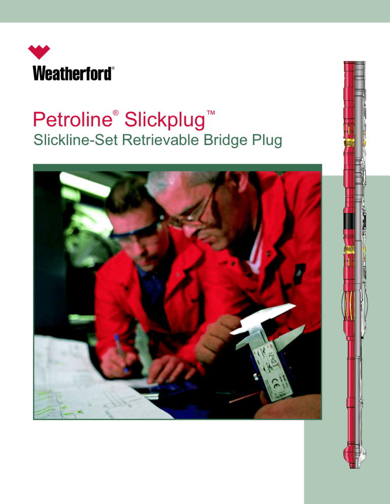
® Petroline Slickplug™ Slickline-Set Retrievable Bridge Plug Petroline Slickplug™ ® Fishing neck Slickplug Retrievable Bridge Plug Upper slips The Slickplug retrievable bridge plug was developed in response to the oil and gas industry’s move toward monobore wells and the requirement for through-tubing retrievable tools to service those completions. The driver behind the development of a plug set on slickline using mechanical manipulation alone was to reduce the operational costs associated with electric line tools, which are set using pyrotechnics. In recognition of the increasing number of high-deviation/horizontal wells, as well as the need for precise depth control on some occasions, a range of adapters evolved for deployment using alternative methods. With the appropriate adapter, the same Slickplug tool can now be set on slick line, electric line, coiled tubing or drillpipe. This flexibility minimizes inventory and maximizes operability. Element Lower slips Since its introduction, the Slickplug tool has seen service all over the world in a variety of applications. During that time, the tool’s reliability has surpassed that of all comparable systems, in particular in the key area of retrievability. The patented release mechanism and element design combine to ensure that the Slickplug tool currently enjoys a failure rate below one percent. Key Features and Advantages Sizes from 2-3/8 in. (50.8 mm) to 7 in. (177.8 mm) nominal are available No need for explosives, timers or radio silence Drag mechanism Standard pressure rating of 5,000 psi (34,473.8 kPa) from above and below; higher ratings available on request One plug can service a wide range of tubing weights The same plug can be set on slick line, electric line, coiled tubing or drillpipe Load transfer sleeve Applications Shallow-set barriers for tree maintenance Contingent plugging of completions with damaged nipples Zonal isolation and water and gas shut-off Tubing leak identification Equalizing assembly Pump-open plug or other flowcontrol device 2 © 2005-2007 Weatherford. All rights reserved. Data acquisition close to the producing interval Petroline Slickplug™ ® Operating Principle Mechanical Setting Tool The Slickplug tool is run on a conventional slickline toolstring. In the running position, both sets of slips are retracted. The plug is lowered close to setting depth, then picked up. Lowering the plug again sets the lower slips, which can be retracted again by picking up the plug. Repeated pickup and set-down of the plug allows depth correlation to be determined. The Slickplug tool can be set using mechanical wireline manipulation alone. Depending on the size of a plug, two different running tools are used. Once the lower slips are set, downward jarring sets the upper slips and partially expands the element. With the upper slips set, upward jarring shears the load transfer sleeve, allowing transfer of the jarring force to the element itself and preventing loss of force through the slips and into the tubing wall. Continued upward jarring fully energizes the element. Finally, the running tool is sheared off the plug. The plug is now set and can be tested. A simple mechanical setting tool is used for Slickplug tools set inside 5-in. nominal tubing and smaller. Conventional wireline jarring provides sufficient energy to fully pack off the element, as illustrated on the following page. Retrieval of the tool with a standard pulling tool and pulling probe requires only light downward jarring to achieve collapse of the element and retrieval of the upper slips. Some time should be allowed for the element to relax before pulling out of hole. Before finally pulling out, the set/unset mechanism is cycled to ensure that the bottom slips will open should the plug be dropped for any reason (for example, a wire break) on the way out of hole. A surface setting tool can also be supplied for occasions when the Slickplug tool must be preinstalled in the tubing string on the surface. Mechanical Setting Tool High-Load Mechanical Setting Tool High-Load Mechanical Setting Tool The high-load mechanical setting tool (MST) is used for Slickplug tools set in 5-1/2 in. nominal tubing and larger. In these cases, jarring alone usually cannot pack off the element well enough to provide full pressure rating from below. The MST is hydraulically primed on surface, although the tool itself contains no seals. When the Slickplug device is at setting depth, mechanical jarring fires the MST, releasing its stored energy. The energy provides the high force needed to pack off the plug element against the tubing wall. © 2005-2007 Weatherford. All rights reserved. 3 Petroline Slickplug™ ® Setting Sequence Pick up and set down to activate drag mechanism and land off the lower slips. 4 © 2005-2007 Weatherford. All rights reserved. Jar down to set top slips. Jar down repeatedly to partially compress element. Jar up to shear load transfer sleeve. Continue upward jarring to fully compress element. Shear off running tool. Petroline Slickplug™ ® Hydraulic Setting Adapter Equalizing Prong In very high step-out horizontal wells on intervention operations can be executed on wireline. For this reason, adapters have been developed to allow setting of the Slickplug tool with pressure and without the need for any jarring impacts. The equalizing prong is run to allow pressure to equalize before pulling the Slickplug tool. Usually a separate equalizing trip is made before pulling the plug on slick-line; however, combined pulling and equalizing prongs may sometimes be used and are routine when pulling the Slickplug tool on coil or drillpipe. The choice of adapter depends on the setting method. The adapter can be activated by means of a dropped ball, by using a suitable circulation/shut-off valve, or by simply running a sealed string. Once the adapter has been activated, pressure applied inside the coil or drillpipe will set the slips, pack off the element, and release the running tool. If necessary, a combination of reduced setting pressure and overpull can be used to set the Slickplug tool. Electric-Line Setting Adapter For some operations such as water shutoff, depth correlation is required to a higher degree of accuracy than can be achieved on slick line. In these cases it may be preferable to run Slickplug tools on electric line, which allows the use of a casing collar locator tool. Consequently, a setting adapter has been developed for use in conjunction with industry-standard pyrotechnic setting tools. With both the electric-line and hydraulic adapters there is no need for the drag mechanism on the Slickplug tool. Removal or addition of the drag mechanism can be performed in the field to maximize operational flexibility. An alternative prong-style equalizing assembly is available on request. Equalizing Assembly The equalizing assembly is made up to the Slickplug tool for use in all standard plugging operations. Its function is to ensure that any pressure differential across the plug can be equalized prior to recovery. The melon in the equalizing assembly is run in place, sealing across the equalizing ports. Prior to recovering the Slickplug tool, the equalizing prong (right) is run to shift the melon off-seat and expose the equalization ports. Differential pressure is equalized through the ports and the plug can then be safely unset and retrieved to surface. © 2005-2007 Weatherford. All rights reserved. 5 Petroline Slickplug™ ® Drift Petroline Pump-Open Plug Weatherford’s Petroline Slickplug drift performs a dual function. The primary function of the drift is to confirm access to the required setting depth prior to running the slickplug tool. The information gained from the drift also allows optimum setting of the power jars to perform within the wireline operating limits. The pump-open plug was designed to enable bringing plugged wells back into production more safely and economically than with conventional wireline plugs. Operated by applied differential pressure from above, the device can be pumped open. The pumpopen plug is designed for a high-accuracy shear rating and reliability even in high-debris conditions. The secondary function of the drift is to act as a junkcatcher above the Slickplug tool. This is achieved by simply reversing the inner sleeve within the bottom sub, therefore closing off the flow ports at the lower end of the drift. The pump-open plug can be run below a Slickplug tool to allow pressure equalization in high-debris conditions without the requirement for an additional wireline run. Junk Catchers Two styles of junk catcher are available for operations in which the Slickplug tool may be exposed to well debris. One is designed to be run below the Slickplug tool’s equalizing assembly to catch any junk that falls through the plug. The second type sits within the fishing neck of the Slickplug tool to prevent debris from entering the plug body. There are two options for top-set junk catchers: with sealing element, and without sealing element. Customized catcher designs are available upon request. Drift 6 Junkcatcher © 2005-2007 Weatherford. All rights reserved. Pulling Probe The pulling probe is run together with a DU- or GS-type pulling tool to retrieve the Slickplug tool after equalization. The probe engages the release mechanism of the plug, which frees the top slips and relaxes the element. The plug can then be easily picked off the bottom slips and pulled out of hole. If the Slickplug tool will be pulled on coiled tubing or drill pipe, a flow-release DU- or GS-type tool may be used together with a ported pulling probe. This arrangement allows the internal components of the Slickplug tool to be washed clear of debris Petroline Slickplug™ ® Specifications Each size of Slickplug tool is designed to set in as wide a range of tubing weight as possible. The outside diameter of the plug has been kept as small as possible to optimize the running clearance for the plug through well completions. The table below lists the sizes of plugs available and the tubing weight range for which each plug is suitable. Should your exact requirement not be specified here, please contact your local Weatherford representative for assistance. Tubing Nominal Size (in./mm ) 2-3/8 60.3 2-7/8 73.0 3-1/2 88.9 4 101.6 4-1/2 114.3 Weight Range (lb/ft) 4.6 to 5.8 6.4 to 7.8 8.6 9.2 to 10.2 9.5 to 11.0 11.6 to 15.1 18.8 to 21.6 15.0 to 18.0 5 127.0 20.3 to 21.4 23.2 to 24.2 17.0 to 23.0 5-1/2 139.7 20.0 to 23.0 23.8 to 26.8 6-5/8 168.3 20.0 to 28.0 23.0 to 32.0 7 177.8 26.0 to 35.0 29.0 to 38.0 32.0 to 41.0 OD* (in./mm ) 1.763 44.800 2.200 55.900 2.160 54.870 2.720 69.088 3.260 82.804 3.600 91.440 3.260 82.804 4.050 102.870 3.980 101.092 3.850 97.790 4.530 115.062 4.462 113.335 4.325 109.855 5.650 143.510 5.930 150.622 5.820 147.828 5.720 145.288 5.650 143.510 Plug Standard Pressure Rating (psi/kPa ) 7,500 51,711 Temperature Rating (°F/°C ) 250 121 7,500 51,711 250 121 5,000 34,474 5,000 34,474 250 121 250 121 5,000 34,474 250 121 5,000 34,474 250 121 5,000 34,474 250 121 5,000 34,474 250 121 5,000 34,474 250 121 *Recommended running clearance is 0.300 in. (0.762 mm) above plug OD. Example: A 5.720-in. (149.29-mm) OD plug will pass a 5.750-in. (146.05-mm) restriction. © 2005-2007 Weatherford. All rights reserved. 7 Weatherford International Ltd. 515 Post Oak Blvd., Suite 600 Houston, Texas 77027 Phone: 713-693-4800 www.weatherford.com Weatherford products and services are subject to the Company’s standard terms and conditions, available on request or at www.weatherford.com. For more information contact an authorized Weatherford representative. Unless noted otherwise, trademarks and service marks herein are the property of Weatherford. Specifications are subject to change without notice. Weatherford sells its products and services in accordance with the terms and conditions set forth in the applicable contract between Weatherford and the client. © 2005-2007 Weatherford. All rights reserved. Brochure 226.02
