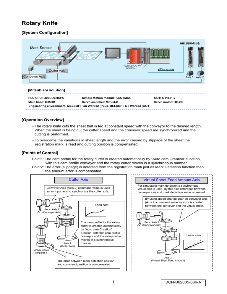
Rotary Knife [System Configuration] Mark Sensor Cutter Axis Conveyor Axis Axis 1 Axis 2 [Mitsubishi solution] PLC CPU: Q06UDEHCPU Simple Motion module: QD77MS4 GOT: GT165*-V Main base: Q35DB Servo amplifier: MR-J4-B Engineering environment: MELSOFT GX Works2 (PLC), MELSOFT GT Works3 (GOT) Servo motor: HG-SR [Operation Overview] - The rotary knife cuts the sheet that is fed at constant speed with the conveyor to the desired length. When the sheet is being cut the cutter speed and the conveyor speed are synchronized and the cutting is performed. - To overcome the variations in sheet length and the error caused by slippage of the sheet the registration mark is read and cutting position is compensated. [Points of Control] Point1: The cam profile for the rotary cutter is created automatically by “Auto cam Creation” function, with this cam profile conveyor and the rotary cutter moves in a synchronous manner. Point2: The error (slippage) is detected from the registration mark just as Mark Detection function then the amount error is compensated. Cutter Axis Virtual Sheet Feed Amount Axis Conveyor Axis (Axis 2) command value is used as an input axis to synchronize the cutter axis. For simulating mark detection a synchronous virtual axis is used. By this axis difference between conveyor axis and mark detection value is created. By using speed change gear on conveyor axis (Axis 2) command value an error is created between the conveyor and the virtual sheet. Feed cam Servo Axis 2 (Conveyor Axis) Axis 1 (Cutter Axis) The cam profile for the rotary cutter is created automatically by “Auto cam Creation” function, with this cam profile conveyor and the rotary cutter moves in a synchronous manner. Servo Axis 2 (Conveyor Axis) Linear cam Virtual Servo Amplifer 4 The error between mark detection position and command position is compensated. 1 Axis 3 (Virtual Sheet Feed Amount) BCN-B62005-666-A [Each Axis Control Detail] - Conveyor Axis: Speed control at constant speed - Cutter Axis: Synchronized with the conveyor axis following a cam pattern (one direction movement) [Operation Flowchart] START Automatic start ON? (GOT) ON Switch Cutter Axis to Synchronous Mode Start Conveyor Axis Cutter → Speed Asynchronous Speed At Cut Area? (180°- α) Y Cutter → Speed 180° - α Synchronous Speed Cut Finished? (180°+ α) Y ON Mark Detection compensation Automatic start OFF? (GOT) 90° 0° Rotary Cutter 180° Synchronous Section Asynchronous Section 270° 180° + α Sheet Moving Direction Operation according to the cam pattern OFF Conveyor Axis Stop Exit Cutter Synchronous END [Operation Time Chart] 1 cam cycle 1 cam cycle 1 cam cycle Sheet Cut Area Sheet Cut Area 1 cam cycle 360° Cutter Angle 180° 0° Cutter Speed Conveyor Speed Sheet Cut Area Synchronous Section Sheet Cut Area 2 Sheet Cut Area BCN-B62005-666-A [Cam Pattern Automatic Generation for Rotary Knife] In ladder program the parameter below set then Automatic Cam Generation is requested. The rotary cutter cam pattern is generated and saved inside the cam number set in the parameters. Setting Item Setting Content (Buffer Mem.) Setting Range Example Settings - Set the request for cam auto-generation. Cam auto-generation request (53200) - The Simple Motion module resets the value to "0" automatically after completion of the cam auto 1:Cam auto-generation request - generation. Cam auto-generation cam No. (53201) Cam auto-generation type (53202) Cam resolution (53204) - Set the No. of the cam to be generated automatically. - Set the type of cam auto-generation. - Set the cam resolution for generating the cam. 1~256 1 1:Cam for rotary cutter 1 256/512/1024/2048/4096/ 8192/16384/32768 (Note-1) Sheet Length - Set the sheet length. (53206, 53207) - Set this value in the cam axis length per cycle. 1~2147483647 2000 [ x 0.1mm] - Set the sheet length of the synchronous section. 1~2147483647 100 [ x 0.1mm] - Set the cycle length of the rotary cutter shaft. 1~2147483647 6000 [ x 0.1mm] 0~2147483647 950 [ x 0.1mm] -5000~5000[0.01%] 0 [%] Sheet synchronization width (53208, 53209) Synchronous axis length (53210, 53211) Synchronization starting point (53212, 53213) Synchronous section acceleration ratio (53214) 256 - Set the length from the beginning of the sheet to the start of the synchronous section. (Note-2) - Set when the synchronous speed in the synchronous section needs to be adjusted. The speed is "Synchronous speed (100% + Acceleration ratio)" in the synchronous section. (Note-1): 200.0mm (Sheet Length) is the initial setting in the sample program. (Note-2): 95.0mm (Synchronization starting point) is the initial setting in the sample program. The ±5mm area from the middle of the sheet length is selected as the synchronous section. 3 BCN-B62005-666-A Synchronous Axis Length Sheet Synchronization Width (10.0mm) Synchronization Starting Point Cutter Axis (Cam Axis) Cutter Axis cycle length (600.0mm) Sheet Feed (95.0mm) Sheet Length (200.0mm) Cam Axis Current Value per Cycle (5.0mm) (5.0mm) Sheet Synchronous Width Sheet Length (200.0mm) ( 10.0mm) t Synchronous Section Acceleration Ratio (When 0% it is as fast as Synchronous Speed) Cutter Axis (Cam Axis)Speed Synchronous Speed (Sheet Feed Speed) t Cam Stroke Ratio (Generated Cam Data) 100% t 0° 180° 4 360° BCN-B62005-666-A [Mark Detection Compensation] The registration marks that are printed equal distances apart (Product length) are detected and the distance between marks are measured. The difference between measured distance and the set cutting length is compensated so that the cutter axis and the conveyor moves synchronously. [Sample Program Control Example] When the sheet length setting is 200mm, and due to stretch, mark is not detected unless conveyor feeds 201mm of sheet. Axis 1 Synchronous Parameter Conveyor Axis Cam Output 201mm Aux. Axis for Compensation 200mm Cam Input Axis Cam Input Axis Current Value Aux. Axis Current Value (for Compensation) Cutter Current Position (Cam Position) 1mm Without Compensation 360° 180° Conveyor Movement Amount (Cam Axis Input Value) Sheet 100mm (100mm) 200mm (200mm) 1mm 201mm (200mm) 201mm (200mm) 2mm 201mm (200mm) 2mm 2mm 3mm 4mm 2mm 5mm Distance between two marks 201mm 201mm 201mm 201mm Mark Detection Value 101mm 302mm 503mm 604mm Compensation Amount -1mm -1mm Registration Mark 705mm -1mm Cutting Position For Mark Compensation Ladder program and Simple Motion setting example, refer to the contents of the following pages. (Ladder Program: Page 16, Mark Detection Settings: Page 9, Synchronous Control Parameters: Page 10, 11) 5 BCN-B62005-666-A [Using the sample program] [Sample program configuration] File name Vol2_R_Cutter_PLC.gxw Description Ladder program Model Q06UDEHCPU Vol2_R_Cutter _Motion.pcw Vol2_R_Cutter _GOT.GTW Motion setting file GOT monitoring data QD77MS4 GT165*-V (640x480) Programming tool MELSOFT GX Works2 MELSOFT GT Works3 (Note): Equipment other than the servo amplifiers and servo motor in the system configuration (page 1) are required to operate sample program. Remove the circuit of amplifier-less operation function when connecting a servo amplifier to check the operation (page 13). [Start-up] 1. Decompress the downloaded files to any folder in your PC. 2. Double clicking decompressed files to open the corresponding engineering tool. 3. Ladder program and GOT monitoring data as default are set for English environment. When using Japanese environment, it's possible to switch to Japanese for ladder program in GX Works2 [Tool] - > [Select Language] menu and for GOT monitoring data in GT Works3 Language change the preview column from [2] to [1]. 4. Change the model settings according models to be used. 5. Write the sample program data to PLC CPU, Simple Motion and GOT. 6. After writing all the programs, reset the PLC CPU. When writing all programs was completed, reset the PLC program. [Operating method] Start operation by using the GOT touch button. When you do not have GOT, operate the device with the appropriate touch button in GT Works3’s simulator (Note) or GX Works2’s device test function. function (Note): When using GX Works3’s simulator function, click on the "communication setup" tab of "Simulator setup" and select “USB” or “CPU(RS-232)” from the pull-down menu of "connection". 1. When you start-up the system, on the GOT screen press “Reset system” button to perform home position return operation. Home position return complete lamp turns on when operation is completed. 2. After home position return operation is completed, press “Start Automatic” button, then automatic operation is started. Automatic operation is also stopped by pressing “Start Automatic” button. 3. When Synchronization Rate Setting is changed from the screen during automatic operation, the cut length becomes "Sheet Length" x "Synchronization Rate" and with that an error occurs between the sheet length setting and cut length (Monitor Screen: Cutting Error) during this situation if the "Mark Compensation" button is pressed on the main screen this Cutting Error is compensated. 4. Each axis can be operated independently by using the JOG touch buttons. 6 BCN-B62005-666-A [GOT:Home screen] [GOT:Main screen] [GOT:Setting screen] [GOT:Monitor screen] [Operation check method] 1. Start the digital oscilloscope function of Simple Motion module setting tool. 2. A trigger condition is automatic operation start (B0). During automatic operation, speed waveform of each axis is registered. 3. Check collected waveforms with operation pattern. Cautions - When diverting the sample program to the actual system, be sure to verify that there are no problems with control in the system. - Add interlock conditions in the target system where considered necessary. 7 BCN-B62005-666-A [Simple Motion Settings] [System Settings] - Axis1: Cutter Axis (MR-J4-B) - Axis2: Conveyor Axis (MR-J4-B) - Axis3: For creating Virtual Sheet Feed Amount (creating Synchronous Error) (Virtual Servo Amplifier) - Axis4: Mark Detection Compensation (Virtual Servo Amplifier) Virtual servo amplifier [Parameters] - Movement amount per motor rotation Cutter axis : 90degree/rev Conveyor axis, Virtual servo amplifier axis : 200mm/rev - Speed limit settings Cutter axis : 90degree/rev × 3000r/min = 270000degree/min (750 sheets/min) Conveyor axis, Virtual servo amplifier axis : 200mm/rev × 3000r/min = 600000mm/min Blue: Defualt Value Black: Settings Made 8 BCN-B62005-666-A [Mark detection settings] Axis2: When the Mark Sensor ON it latches the Conveyor Axis current position. (Note): There is no Mark Detection signal connected to the input for this sample program simulation. For simulation purposes an artificial mark signal is generated inside the PLC program. That’s why only these Mark Detection settings are made. [Positioning data] Value that could be changed by PLC ladder program Axis 1: Cutter axis home position return (Main point return) Axis 2: Conveyor axis automatic operation During Automatic Operation Speed Control is done at conveyor speed (GOT setting) Axis 4 Virtual servo amplifier: Mark detection compensation By using Mark Detection the real sheet length (Distance between marks) and Sheet length setting difference is calculated. Then by this value the set cutting length is compensated. 9 BCN-B62005-666-A [Synchronous control parameter] Axis 1:Cutter Axis Synchronization is realized by setting the conveyor axis (Servo Input Axis 2) as the main shaft axis. Cam axis 1 cycle length is set to sheet length, and cam stroke is set to 360 degrees. When conveyor axis (Main Shaft) send sheet length, the cutter axis turns for one rotation (360 degrees), so that the sheet is cut at the set sheet length. The gap between the Output axis and Conveyor axis (Main Shaft) during mark detection is compensated by the auxiliary axis which is set to virtual Axis 4. CAM Pattern Cam pattern The settings below are made from ladder program. The cam used for Rotary Cutter is generated automatically. Auto Generation 10 BCN-B62005-666-A Axis 3 (Virtual Servo): Used for generating Virtual Sheet amount. Conveyor axis difference is created by using a speed change gear regarding to the conveyor axis. Then this value is used for mark detection compensation simulation purpose. The denominator of Speed Change Gear set to 1000, the numerator is set from the GOT synchronization ratio parameter. ex: When the synchronization ratio parameter is set to 100.5[%] from the GOT, the numerator becomes 1005, in this case the output axis moves for 100.5 mm as opposed to the conveyor axis which moves 100 mm. Shaft axis is set as the conveyor axis (Servo Input Axis 2) At every time current position of Axis 3 (Virtual Sheet) is proportional to the set sheet length the virtual mark sensor signal turns ON. Then the mark detection processing is executed (Conveyor axis current position is latched). Linear cam: The command coming from the output of the speed change gear is directly outputted as it is. 11 BCN-B62005-666-A [Sample ladder program configuration] [MAIN: Scan Execution] START Initial data processing QD77MS Simple Motion startup processing JOG operation processing Home positioning return processing Automatic operation processing 1: Automatic rotary cutter cam generation setting Automatic operation processing 2: Cutter axis synchronous control start processing Automatic operation processing 3: Conveyor axis start processing Automatic operation processing 4: Mark detection compensation processing Automatic operation processing 5: Stop processing Positioning start signals processing GOT monitor signal used processing Error reset processing END [Mark_Sim: 0.5ms fixed cycle] Mark detection simulation START Virtual sheet feed generation axis synchronous control start Initial data setting process during automatic start processing Virtual sheet cut measurement detection processing Virtual mark position detection processing END [Devices used in this program] Device No. B0 B1 B2 B4 B5 B6 B11 B12 B21 B22 W0 W1 W2 W3 WA W10 W12 Content Automatic Operation Start (GOT) Home Position Return (GOT) Error Reset (GOT) Mark Detection compensation ON/OFF (GOT) Home Position Return Completion (GOT) Error Lamp (GOT) Cutter Axis JOG forward (GOT) Cutter Axis JOG reverse (GOT) Conveyor Axis JOG forward (GOT) Conveyor Axis JOG reverse (GOT) Cutter Axis JOG Speed setting (GOT): x 0.001 [degree/min] Conveyor Axis JOG Speed Setting (GOT): x 0.01 [mm/min] Current Production Monitor (GOT): [sheet] Sheet Length Setting (GOT): x 0.1 [mm] Conveyor Speed Setting 12 Device No. M1 M2 M5 M11 Cutter Axis HPR Start Conveyor Axis HPR Start Automatic Conveor Axis Start Cutter Axis in Synchronous Control M20 Mark Compensation Start Possible M21 D0 D1 D2 D3 D4 D5 D6 D7 D1050 Mark Compensation Start Last Mark Detection Counter Value Content Last (Recent) Mark Detection Value Distance between two mark detection x0.1 [μm] Mark Detection Compensation Amount x0.1 [μm] Temporary calculation BCN-B62005-666-A [Ladder program] 1. MAIN Initial Settings:Initialization of the input devices in GOT Cutter Axis JOG Speed: 3600.000deg/min (10r/min) Conveyor Axis JOG Speed: 600mm/min (10mm/sec) Remove these lines to use real servo amplifier. Sheet Length: 200.0mm Conveyor Speed: 20.0m/min For simulation purposes amplifier-less mode is selected. Fixed Cycle Program (Mark Sim) Is enabled. QD77MS Simple module Motion module start-up QD77MS Start All Axis Servo ON Command 13 BCN-B62005-666-A JOG operation Cutter Axis JOG Speed Setting Axis 1 Forward JOG Command ON Axis 1 Reverse JOG Command ON Conveyor Axis JOG Speed Setting Axis 2 Forward JOG Command ON Axis 2 Reverse JOG Command ON Home Position Return Cutter Axis When HPR is not completed Positioning No.9001 (HPR) is set. When HPR is completed Positioning No.1 (Move to 0 degree) is set. Positioning Point: 0 degree is set. Positioning Start Flag ON Conveyor Axis Positioning No.9001 (HPR) is set. Positioning Start Flag ON 14 BCN-B62005-666-A Automatic Operation 1: Automatic Rotary Cutter Cam Generation Setting [Cd.609] Auto cam Generation No. Setting 1: No.1 [Cd.610] Auto cam Generation Type 1: Rotary Cutter cam [Cd.611] Auto cam Generation parameter cam Resolution: 256 [Cd.611] Auto cam Generation parameter Sheet Length: Setting from GOT (W10) [Pr.439] cam Axis 1 Length per cycle 1 Cycle Length: Sheet Length [Cd.611] Auto cam Generation parameter Sheet Synchronization Width: 10.0mm [Cd.611] Auto cam Generation parameter Synchronous Axis Length: 600.0mm [Cd.611] Auto cam Generation parameter Synch Start Pos: (Sheet Length/2)-5.0mm *A center position of the length of a set seat is set as the cutting position and cutting position ±5.0mm is taken as synchronous width. [Cd.611] Auto cam Generation parameter Acc. Ratio in Synchronous section: 0.00% [Cd.608] Auto cam generation request Automatic Operation 2: Cutter Axis Synchronous Control start processing Cutter Axis Synchronization Request Cutter Axis In Synchronization Status 15 BCN-B62005-666-A Automatic Operation 3: Conveyor Axis Startup processing [Conveyor Axis Speed] Screen Speed Setting -> Command Speed Axis 2 Position No.1 is set Axis 2 Positioning Start Flag ON Automatic Operation 4: Mark Detection compensation processing When Automatic Operation Starts or Mark Compensation is started the values are initialized as the last values. Mark Detection Counter Value Current Value → Last Value Mark Detection Data Current Value → Last Value External Command Enable When the Mark Detection Counter Value changes The difference of Distance Between Marks (Detection Value: Current Value - Last Value) and Standard Value (Set sheet length) is calculated. Distance between marks (Real Sheet Length) Calculation Mark Detection Value: Current- Last Value Compensation Amount Calculation Set Sheet Length - Real Sheet Length Mark Detection Counter Value Last Value Update Mark Detection Data Last Value Update While Cutter Angle is between 0 to 100° start positioning for compensation. Virtual servo amplifier axis 4 Positioning No.1 is set. Virtual servo amplifier axis 4 Compensation Amount -> Positioning Amount Virtual servo amplifier axis 4 Positioning Start Flag ON 16 BCN-B62005-666-A Automatic Operation 5: Stop processing [Conveyor Axis] When auto operation is OFF, stop command is set. When the BUSY signal is OFF, stop command is reset. Positioning Start Signal processing [Cutter Axis] During HPR, axis 1 starts. [Conveyor Axis] During auto start or HPR, axis 2 starts. [Cutter Axis Synchronous Aux. Axis] During mark detection compensation, virtual axis 4 starts. Monitor Signal used in GOT processing Home Position Return Complete Flag When all axes HPR request are OFF and cutter axis's current angle is 0°, this flag turns ON. Error Flag Turns on when error is detected in an axis. Count up when an angle of cutter passes 180° during automatic operation. Error Reset processing 17 BCN-B62005-666-A 2. Mark_Sim (For Mark Detection Simulation:0.5ms fixed cycle program) Virtual sheet feed generation axis synchronous control start processing During automatic operation starts, synchronous control of Virtual Servo Amplifier Axis 3 starts. Initial data setting process during Auto Start processing Mark Detection Counter Axis 3 Current Value → Last Value Mark ON Address Axis 3 Current Value → ON Address Mark OFF Address ON Address+10mm → OFF Address Virtual sheet cut measurement detection processing During Cutting (When cutter passes 180°) Axis 3 Current Value Current Value- Last Value → Cut Measurement Axis 3 Current Value Current Value → Last Value Virtual Mark Position detection processing Virtual Mark Sensor ON Processing Axis 2 (Conveyor Axis) Current Value latch → Mark Detection Data [Virtual Mark Sensor ON Condition] Turn ON when Axis 3 send set sheet length turns OFF when Axis 3 sends set sheet length +10mm. Mark Detection Counter Count Up Virtual Mark Sensor OFF Processing Mark ON Address Current ON address + Sheet length → Next ON Address Mark OFF Address Next ON address + 10mm → Next OFF address END 18 BCN-B62005-666-A


