IRJET- E Shape Patch Antenna Array
advertisement

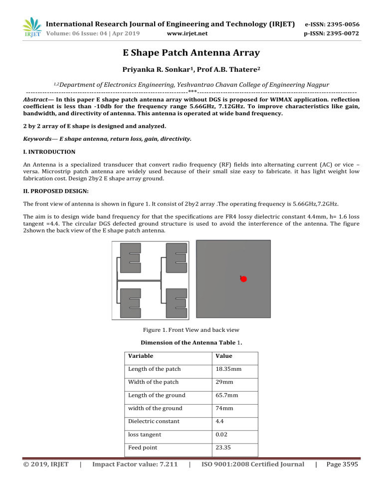
International Research Journal of Engineering and Technology (IRJET) e-ISSN: 2395-0056 Volume: 06 Issue: 04 | Apr 2019 p-ISSN: 2395-0072 www.irjet.net E Shape Patch Antenna Array Priyanka R. Sonkar1, Prof A.B. Thatere2 1,2Department of Electronics Engineering, Yeshvantrao Chavan College of Engineering Nagpur ---------------------------------------------------------------------***-------------------------------------------------------------------- Abstract— In this paper E shape patch antenna array without DGS is proposed for WIMAX application. reflection coefficient is less than -10db for the frequency range 5.66GHz, 7.12GHz. To improve characteristics like gain, bandwidth, and directivity of antenna. This antenna is operated at wide band frequency. 2 by 2 array of E shape is designed and analyzed. Keywords— E shape antenna, return loss, gain, directivity. I. INTRODUCTION An Antenna is a specialized transducer that convert radio frequency (RF) fields into alternating current (AC) or vice – versa. Microstrip patch antenna are widely used because of their small size easy to fabricate. it has light weight low fabrication cost. Design 2by2 E shape array ground. II. PROPOSED DESIGN: The front view of antenna is shown in figure 1. It consist of 2by2 array .The operating frequency is 5.66GHz,7.2GHz. The aim is to design wide band frequency for that the specifications are FR4 lossy dielectric constant 4.4mm, h= 1.6 loss tangent =4.4. The circular DGS defected ground structure is used to avoid the interference of the antenna. The figure 2shown the back view of the E shape patch antenna. Figure 1. Front View and back view Dimension of the Antenna Table 1. © 2019, IRJET | Variable Value Length of the patch 18.35mm Width of the patch 29mm Length of the ground 65.7mm width of the ground 74mm Dielectric constant 4.4 loss tangent 0.02 Feed point 23.35 Impact Factor value: 7.211 | ISO 9001:2008 Certified Journal | Page 3595 International Research Journal of Engineering and Technology (IRJET) e-ISSN: 2395-0056 Volume: 06 Issue: 04 | Apr 2019 p-ISSN: 2395-0072 www.irjet.net III. Simulation Results: S11 Parameter S parameter is scattering parameter refers to a way in which the travelling current and voltages in transmission line. S11 parameter represents how much power is reflected from the antenna, and hence is known as reflection coefficient. If S11 is equal to 0dB then all the power is reflected from the antenna and nothing radiated. If S11 is equal to -10db this implies that 3dB of power is delivered to antenna and -7dB is reflected power. VSWR: © 2019, IRJET | Impact Factor value: 7.211 | ISO 9001:2008 Certified Journal | Page 3596 International Research Journal of Engineering and Technology (IRJET) e-ISSN: 2395-0056 Volume: 06 Issue: 04 | Apr 2019 p-ISSN: 2395-0072 www.irjet.net Total Field Property 5.66GHz Gain 3.7 Directivity 9.04 7.12GHz Gain 6.2 Directivity 9.4 IV. Conclusion Eshape microstrip patch antenna gives better performance at 5.6GHz ,and 7.12GHz frequency. The antenna can used for wireless communication . V. Acknowledgment The author wish to acknowledge the assistance and support of Yeshwantrao Chavan College of Engineering Nagpur, India. VI. References • Anil Kumar Dubey ,” Array Of E Shaped Patch Antenna with DGS”.987-1-5090-4708-6/7/$31 2017 IEEE IRISWORLD,july 01-02-2017 • Anil Kumar Dubey ,”Optimization microstrip Patch antenna using array”, IJSER 15511,vol10,2015 • Anil Kumar Dubey ,”Bandwidth enhancement of Patch antenna of using array “. International Journal for Scientific Research & Development, IJSRD, 158605, vol 10, 2015. • A.R.Mallahzadeh,S Eshanghi and A.Alipour of “E shaped MIMO antenna using IWO algorithm for wireless application at 5-8GHz”.PIER 90,187-203,2009 © 2019, IRJET | Impact Factor value: 7.211 | ISO 9001:2008 Certified Journal | Page 3597 International Research Journal of Engineering and Technology (IRJET) e-ISSN: 2395-0056 Volume: 06 Issue: 04 | Apr 2019 p-ISSN: 2395-0072 www.irjet.net • B.K Ang and B.K chung “A wide band E- Shaped microstrip patch antenna for 5-6GHz wireless communication”.PIER 75,397-407,2007Md. Muzammil Adnan1 Siddarama R. Patil, “Design and Analysis of Micro Strip patch Antenna with optimization for Wireless Communication”. International Journal for Scientific Research & Development, IJSRD, Vol. 2, Issue 07, page no. 138- 141, 2014. • George Casu, Catalin Moraru, Andrei Kovacs, “Design and Implementation of Microstrip Patch Antenna Array”. Communications (COMM), 10th International Conference, page no. 1-4, 2014 • S. Xiao M.-C. Tang Y.-Y. Bai S. Gao B.-Z. Wang. “Mutual coupling suppression in microstrip array using defected ground structure”. IET Microw. Antennas Propag, Vol. 5, Issue 12, page no. 1488–1494, 2011. © 2019, IRJET | Impact Factor value: 7.211 | ISO 9001:2008 Certified Journal | Page 3598


