C4XL10-D240-PR
6.92 [176]
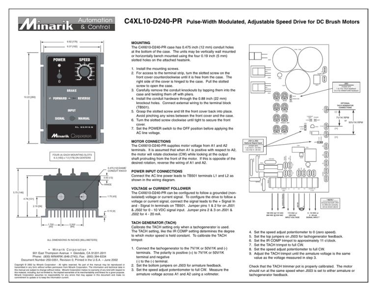
MOUNTING
The C4X610-D240-PR case has 0.475 inch (12 mm) conduit holes
at the bottom of the case. The units may be vertically wall mounted
or horizontally bench mounted using the four 0.19 inch (5 mm)
slotted holes on the attached heatsink.
6.37 [162]
SPEED
MANUAL
XL SERIES
Corporation
MOTOR CONNECTIONS
The C4X610-D240-PR supplies motor voltage from A1 and A2
terminals. It is assumed that when A1 is positive with respect to A2,
the motor will rotate clockwise (CW) while looking at the output
shaft protruding from the front of the motor. If this is opposite of the
desired rotation, reverse the wiring of A1 and A2.
FOUR (4) EACH MOUNTING SLOTS
6.3 [160] x 7.0 [178] ON CENTERS
0.475 [12] DIAMET
CONDUIT KNOCK
0.50 [13]
TACH
ARMATURE
IL502
2.19 [56]
0.15 [4]
1.700
[43]
2.500
[64]
ALL DIMENSIONS IN INCHES [MILLIMETERS]
• Minarik Corporation •
901 East Thompson Avenue • Glendale, CA 91201-2011
Phone: (800) MINARIK (646-2745); Fax: (800) 394-6334
Document Number 250-0351, Revision 0; Printed in the U.S.A. – June 2002
Copyright © 2002 by Minarik Corporation - All rights reserved. No part of this manual may be reproduced or
transmitted in any form without written permission from Minarik Corporation. The information and technical data in
this manual are subject to change without notice. Minarik Corporation makes no warranty of any kind with respect to
this material, including, but not limited to, the implied warranties of its merchantability and fitness for a given purpose.
Minarik Corporation assumes no responsibility for any errors that may appear in this document and make no
commitment to update or to keep the information current.
(+)
0-10V
SIGNAL OFFSET TACH
J501 & J502
Optional Signal Input
100V/1K
(+)
J501
Jumper pins
1 & 2 for 0 - 10 VDC
2 & 3 for 4 - 20 mA
C501
T501
S3
S2
MOV502
F502
POWER INPUT CONNECTIONS
Connect the AC line power leads to TB501 terminals L1 and L2 as
shown in the wiring diagram.
Q503
S1
A1
C502
F501
MOV501
VOLTAGE or CURRENT FOLLOWER
The C4X610-D240-PR can be configured to follow a grounded (nonisolated) voltage or current signal. To configure the drive to follow a
voltage or current signal, connect the signal leads to the + Signal In
and - Signal In terminals on TB501. Jumper pins 1 & 2 for on J501
& J502 for 0 - 10 VDC signal input. Jumper pins 2 & 3 on J501 &
J502 for 4 - 20 mA.
1. Connect the tachogenerator to the 7V/1K or 50V/1K and (-)
terminals. The polarity is positive (+) to 7V/1K or 50V/1K
terminal and negative
(-) to the (-) terminal.
2. Set the bottom jumpers on J503 for armature feedback.
3. Set the speed adjust potentiometer to full CW. Measure the
armature voltage across A1 and A2 using a voltmeter.
7V/1K
IC501
4-20mA
A2
TACH GENERATOR (TACH)
Calibrate the TACH setting only when a tachogenerator is used.
The TACH setting, like the IR COMP setting determines the degree
to which motor speed is held constant. To calibrate the TACH
trimpot:
7V/1K RPM
or
50V/1K RPM
IL501
J502
F2
F1
CHASSIS
GND
CHASSIS GROUND
1.70 [43]
4.78 [121]
(-)
CURRENT
POWER
LIMIT
HINGE
5.75 [146]
OPTIONAL
TACH GENERATOR
CONNECTIONS
-
0-10V
SIGNAL
Q501
4-20mA
INPUT
Jumper pins
1 & 2 for TACH feedback
2 & 3 for ARMATURE feedback
INHIBIT
REVERSE
IC502
FORWARD
J503
R501
C507
FROM REV SW
BRAKE
10.22 [260]
A2
C505
L2
L1
A2
A1
+ SIGNAL IN 0-10V
* NOTE *
MOTOR
100
A1
Q502
TO
PWR SW
90
L1
10
1. Install the mounting screws.
2. For access to the terminal strip, turn the slotted screw on the
front cover counterclockwise until it is free from the case. The
right side of the cover is hinged to the case. Pull the slotted
screw to open the case.
3. Carefully remove the conduit knockouts by tapping them into the
case and twisting them off with pliers.
4. Install the conduit hardware through the 0.88 inch (22 mm)
knockout holes. Connect external wiring to the terminal block
(TB501).
5. Grasp the slotted screw and tilt the front cover back into place.
Avoid pinching any wires between the front cover and the case.
6. Turn the slotted screw clockwise until tight to secure the front
cover.
7. Set the POWER switch to the OFF position before applying the
AC line voltage.
L2
80
FROM
PWR SW
70
20
TB501
30
0
D501
60
TH501
50
C503
40
C504 C506
TH502
POWER
Pulse-Width Modulated, Adjustable Speed Drive for DC Brush Motors
Ensure that both J501
& J502 are correctly
set as shown above
+
M
100 VDC @ 115 VAC
200 VDC @ 230 VAC
4.
5.
6.
7.
8.
9.
115 VAC or
230 VAC
INPUT VOLTAGE
0 - 10 VDC or
4 - 20 mA
SIGNAL INPUT *
Set the speed adjust potentiometer to 0 (zero speed).
Set the top jumpers on J503 for tachogenerator feedback.
Set the IR COMP trimpot to approximately 11 o’clock.
Set the TACH trimpot to full CW.
Set the speed adjust potentiometer to full CW.
Adjust the TACH trimpot until the armature voltage is the same
value as the voltage measured in step 3.
Check that the TACH trimmer pot is properly calibrated. The motor
should run at the same speed when J503 is set to either armature or
tachogenerator feedback.


