Designing high-temperature differential amplifier
advertisement

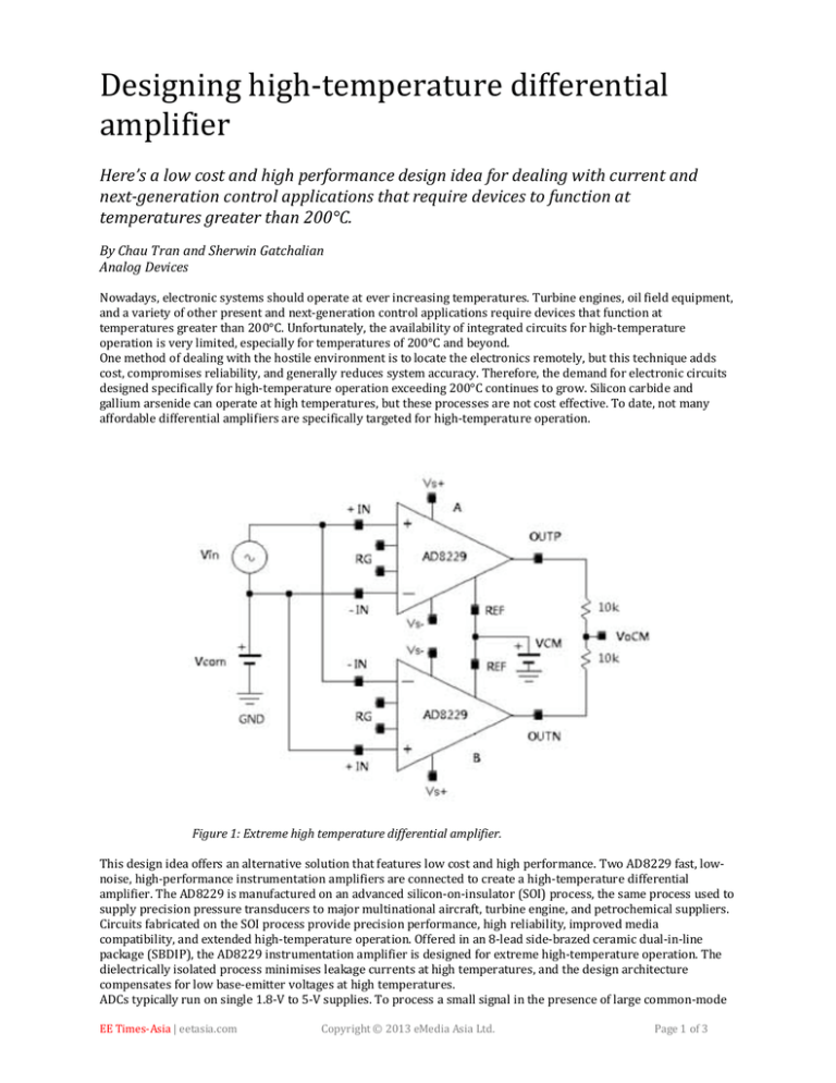
Designing high-temperature differential amplifier Here’s a low cost and high performance design idea for dealing with current and next-generation control applications that require devices to function at temperatures greater than 200°C. By Chau Tran and Sherwin Gatchalian Analog Devices Nowadays, electronic systems should operate at ever increasing temperatures. Turbine engines, oil field equipment, and a variety of other present and next-generation control applications require devices that function at temperatures greater than 200°C. Unfortunately, the availability of integrated circuits for high-temperature operation is very limited, especially for temperatures of 200°C and beyond. One method of dealing with the hostile environment is to locate the electronics remotely, but this technique adds cost, compromises reliability, and generally reduces system accuracy. Therefore, the demand for electronic circuits designed specifically for high-temperature operation exceeding 200°C continues to grow. Silicon carbide and gallium arsenide can operate at high temperatures, but these processes are not cost effective. To date, not many affordable differential amplifiers are specifically targeted for high-temperature operation. Figure 1: Extreme high temperature differential amplifier. This design idea offers an alternative solution that features low cost and high performance. Two AD8229 fast, lownoise, high-performance instrumentation amplifiers are connected to create a high-temperature differential amplifier. The AD8229 is manufactured on an advanced silicon-on-insulator (SOI) process, the same process used to supply precision pressure transducers to major multinational aircraft, turbine engine, and petrochemical suppliers. Circuits fabricated on the SOI process provide precision performance, high reliability, improved media compatibility, and extended high-temperature operation. Offered in an 8-lead side-brazed ceramic dual-in-line package (SBDIP), the AD8229 instrumentation amplifier is designed for extreme high-temperature operation. The dielectrically isolated process minimises leakage currents at high temperatures, and the design architecture compensates for low base-emitter voltages at high temperatures. ADCs typically run on single 1.8-V to 5-V supplies. To process a small signal in the presence of large common-mode EE Times-Asia | eetasia.com Copyright © 2013 eMedia Asia Ltd. Page 1 of 3 voltages, an instrumentation amplifier ahead of the ADC amplifies the signal while rejecting the common-mode to keep it from saturating the ADC inputs. Figure 1 shows a fully differential amplifier with a system gain of 2. Used with single-ended or differential inputs, it provides a low-distortion differential output that can drive highprecision ADCs. This complete high-temperature solution provides an amplified and scaled output that can greatly improve the performance and operational efficiencies of systems operating in hostile high temperature environments. Amplifier A serves as a follower and amplifier B as an inverter, creating a gained differential signal between OUTP and OUTN. The system defaults to G = 2 when no gain resistor is used. If a gain larger than 2 is desired, add matched gain-setting resistors across the RG terminals. The transfer function of this circuit is VOUT = 2 × G × (VIN+ − VIN−) + VREF where: G = 1 + 6 kΩ/ RG Gain accuracy is determined by the absolute tolerance of RG. The mismatch of the temperature coefficient of the external gain resistors and the internal thinfilm resistors increases the gain drift of the instrumentation amplifiers. Gain error and gain drift are kept to a minimum when the gain resistor is not used. The ability to set different gains affords the user design flexibility. The system gain, G, using several standard resistance values, is shown the table. Note that it requires two gain-setting resistors to set the gain of the system and the resistors must be rated for hightemperature operation. Table: Gain achieved using 1% standard resistor values. Figure 2: Differential outputs are 180% out of phase with each other at 225°C. EE Times-Asia | eetasia.com Copyright © 2013 eMedia Asia Ltd. Page 2 of 3 The ability of this differential amplifier to reject a common-mode voltage is determined by the ratio match of internal laser-trimmed resistors; the closer the match, the higher the common-mode rejection (CMR). With discrete amplifiers and 0.1% external resistors, CMR is limited to 54 dB, but this circuit can achieve CMR better than 86 dB. The common-mode rejection of instrumentation amplifiers typically falls off at 200Hz. This circuit can reject common mode over a greater frequency range, 80 dB CMRR minimum up to 5kHz. With single-supply ADCs and other components, the only circuit requiring dual supplies was the interface at the front end. When used with a dual power supply, this circuit can measure small signals while rejecting large negative common-mode voltages. The output can be level shifted by applying a positive voltage to the REF pins. With a single-supply ADC operating on 5 V, for example, a 2.5-V source on the REF pin sets the output to midsupply. This source, which can be the reference from the ADC, should be low impedance to avoid degrading the CMR and low drift to maintain accuracy over temperature. The low offset and high CMR over frequency of this circuit make it an excellent candidate for bridge measurements. The bridge can be connected directly to the inputs of the amplifier. It can also be used for voltage-output pressure transducers. Since it delivers low noise and low drift, it also serves diagnostic applications. Note that the AD8229 is guaranteed up to 210°C. These experiments were conducted beyond 210°C for informational purposes only. Figure 3: Voltage at VoCM shows output balance error, 0.5mV/div, at 225°C. The mismatch of two outputs is measured at node “VoCM” which is set by the potential of the external source VCM. Figure 3 shows the common mode error of the output. About the author Chau Tran joined Analog Devices in 1984, where he works in the Instrumentation Amplifier Products (IAP) Group in Wilmington, MA. In 1990, he graduated with an MSEE degree from Tufts University. Chau holds more than 10 patents and has authored more than 10 technical articles. EE Times-Asia | eetasia.com Copyright © 2013 eMedia Asia Ltd. Page 3 of 3
