PDF - Motortech GmbH
advertisement

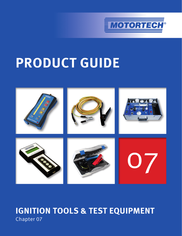
® PRODUCT GUIDE 07 REV. 06/2013 IGNITION TOOLS & TEST EQUIPMENT Chapter 07 07/1 IGNITION TOOLS & TEST EQUIPMENT SparkView MOTORTECH HIGH VOLTAGE INDICATOR The SparkView is a handheld device developed by MOTORTECH that can monitor the high voltage required by the spark plug while the engine is running. With a measuring clamp or cable and the display for up to 40 kV, it is easy to determine the condition of the spark plugs and the time at which they need to be replaced. This guarantees a constant performance of the engine and a maximum utilization of the spark plugs. Quick and comfortable monitoring on a running engine makes it possible to detect • Wear of spark plugs • Failure of the ignition system (damaged ignition coil, spark plug lead or ignition controller) • Faulty compression of a cylinder SparkView – High Voltage Indicator P/N Figure 1 SparkView high voltage indicator incl. SparkScan1 high voltage clamp P/N 06.90.100 06.90.099-105 2 SparkView high voltage indicator incl. BNC cable P/N 06.90.105 1 07/2 Description 06.90.099-100 2 SparkScan1 MOTORTECH HIGH VOLTAGE CLAMP SparkScan1 is designed for operators who want to monitor their high voltage traces in a simple way. The inductive high voltage clamp is connected to a Scope. When attaching the clamp to a conventional spark plug wire (7mm), the probe measures the high voltage pulse and via scope screen the operator can analyse the trace. Measuring high voltage peak (kV) and spark duration (µsec) of all cylinders of an engine in a routine manner, will allow preventive maintenance of the equipment. SparkScan1 – High Voltage Clamp P/N Description Length 06.90.100 SparkScan1 high voltage clamp 2.0 m/7.0 ft. Scope Meter – Digital Oscilloscope The Digital scopemeter is a compact 20 MHz or 40MHz two channel scope. Ideal for troubleshooting of industrial machinery, instrumentation, control and power systems. The Scopemeter has unique features like connect-and-view and trendplot that simplify taking measurements and reduce troubleshooting time when working in the field or in industrial environments. Digital Scope Meter P/N Description 06.98.005-110 Digital scope meter - 110V 06.98.005-220 Digital scope meter - 220V BNC Cable for use with SparkView or Scope Meter P/N Description Length 06.90.105 BNC cable 2.0 m/7.0 ft. 07/3 IGNITION TOOLS & TEST EQUIPMENT ICT MOTORTECH IGNITION COIL TESTER This test equipment is designed to offer service companies a professional tool to test all different kinds of ignition coils that were sold by engine manufacturers or aftermarket companies. A built in CD ignition, high voltage clamp and a spark gap allow realistic testing. Ignition Coil Tester P/N Description 06.98.054 Ignition coil tester incl. adaptor kits for popular ignition coils Adaptor Kits1) – Standard – including Teflon Ignition Coil Adaptors and Connecting Leads 1) P/N Description 06.98.054-1 Connections of included Lead Ignition Coil Ignition Coil Tester Adaptor kit - CATERPILLAR® ignition coils DEUTSCH® connector XLR connector 06.98.054-2 Adaptor kit - ALTRONIC® style ignition coils 2 pole XLR connector 06.98.054-3 Adaptor kit - MOTORTECH style ignition coils 2 pole XLR connector 06.98.054-4 Adaptor kit - Flange ignition coils MIL Style 3 pole socket, 180° XLR connector 06.98.054-5 Adaptor kit - Integral ignition coils, outer thread MIL Style 2/3 pole socket, 180° XLR connector 06.98.054-6 Adaptor kit - Integral ignition coils, inner thread MIL Style 2/3 pole socket, 180° XLR connector 06.98.054-7 Adaptor kit - Externally mounted ignition coils MIL Style 2/3 pole socket, 180° XLR connector All adaptor kits included in ignition coil tester. Adaptor Kits – Special – including Connecting Leads 07/4 Connections of included Lead P/N Description Ignition Coil Ignition Coil Tester 06.70.192-5 Adaptor kit - CUMMINS® ignition coil P/N 3964547 4 pole, 180° XLR connector 06.70.192-6 Adaptor kit - GE JENBACHER® ignition coil P/N 369083 4 pole, 180° XLR connector IPS MOTORTECH IGNITION PICKUP SIMULATOR Anyone trying to troubleshoot electronic ignition systems has come to the conclusion that there are so many different things that can create problems. The ignition pickup simulator allows the operator to simulate all pickup signals that are supposed to be generated by the different pickups installed on flywheel and camshaft. This way the ignition can actually be triggered with the appropriate amount of trigger events while the engine is not cranking. The IPS can be programmed for single and multiple pickup signal frequency. A variety of adaptor harnesses is available to allow use of the IPS with different ignition controller brands and models. IPS – Ignition Pickup Simulator P/N Description 07.98.047 IPS Ignition Pickup Simulator Adaptor Harnesses1) for IPS Ignition Pickup Simulator P/N IPS Adaptor Harness for use with 07.70.001 WOODWARD® IC9xx series 07.70.002-1 MOTORTECH MIC500 series (P/N 06.00.508), WOODWARD® IC100 series with inductive pickup 07.70.002-2 MOTORTECH MIC500 series (P/N 06.00.508), WOODWARD® IC100 series with Hall effect pickup 07.70.002-3 MOTORTECH MIC500 series (P/N 06.00.508), WOODWARD® IC100 series with magnetic pickup 07.70.003 MOTORTECH MIC500 series (P/N 06.00.510) 07.70.004 MOTORTECH MIC500 series (P/N 06.00.513, 06.00.514), ALTRONIC® DIS & DISN, CATERPILLAR® 163-6164, 163-6108 07.70.005 FAIRBANKS MORSE® IQ250 series 07.70.006 ALTRONIC® CPU95 series 07.70.009 MOTORTECH MIC500 series (P/N 06.00.511) 07.70.010 MOTORTECH MIC500 series (P/N 06.00.515-6, 06.00.515-8, 06.00.516, 06.00.517), WAUKESHA® CEC (VHP/VGF series) 07.70.011 MOTORTECH MIC3 series (P/N 66.00.310-6/-12), MIC4 series (P/N 66.00.424-8/-16), MIC5 series (P/N 66.00.541-20) 07.70.012 FAIRBANKS MORSE® IQ750 series 07.70.013 MOTORTECH MIC500 series (P/N 06.00.520, 06.00.525, 06.00.530) 07.70.014 MOTORTECH MIC850 series 07.70.015 MOTORTECH MIC4 series (66.00.400-/410-/440-8/-16), MIC5 series (P/N 66.00.540-20, 66.00.542-20) 1) Need to be ordered separately. 07/5 IGNITION TOOLS & TEST EQUIPMENT Test Adaptor for MIC3, MIC4 and MIC5 Series Ignition Controller To enable operators and service personnel to check input signals to the ignition controller in a simple way, MOTORTECH offers a Test Adaptor that links between the 35 pole input connector and the appropriate harness. Terminals located around the test box allow easy access to each input signal entering the ignition controller. By use of a commonly used Digital Scope Meter, the following signals can be checked: • Input voltage • Analog input signal (4-20mA) • Pickup signals • Start/Stop signal • Go/NoGo signal • Timing schedule selection switch (A/B) 07/6 P/N Description For use with specific controllers 06.98.130 Test adaptor MIC3 (P/N 66.00.310-6/-12) MIC4 (P/N 66.00.424-8/-16) MIC5 (P/N 66.00.541-20) ScopeLite MOTORTECH TIMING LIGHT The self-powered ScopeLite is designed to work with fully shielded ignition systems. A special clamp picks up the small trigger signal through the braid of conventional or MOT-Blues shielded spark plug leads. The signal is processed by the timing light and via LED technology a sequence of flashes is generated. On applications where MOTORTECH flange ignition coils with diagnostic interface are used, the ScopeLite can be attached directly to the BNC connector of the ignition coil. Even on applications with integral or standard flange ignition coils, the clamp can be attached to the shielded primary lead. When timing is checked on engines with non-shielded spark plug leads, a selector switch needs to be pushed which then steps down sensitivity. The automatic time based shut-off function saves the 2 built in 9 V batteries in case the operator forgets to turn off power. Make it easy and safe for the operator! ScopeLite – MOTORTECH Timing Light P/N Description 06.98.100-200 ScopeLite LED timing light, incl. clamp, 200 in. standard connecting lead and carrying case Connecting leads (Standard and Non Standard Lengths1)) P/N Description Length 06.90.104-100 ScopeLite connecting lead 100 in. 06.90.104-200 ScopeLite connecting lead 200 in. 06.90.104-300 ScopeLite connecting lead 300 in. 06.90.104-400 ScopeLite connecting lead 400 in. 06.90.104-600 ScopeLite connecting lead 600 in. 1) If non standard length is required, please order separately from above chart. Use with MOT-Blues shielded spark plug leads. Use with conventional shielded spark plug leads. Use with MOTORTECH flange ignition coils with diagnostic interface or with shielded primary lead. Conversion 1 inch = 25,4 mm / 1 foot = 0,3 m 07/7 IGNITION TOOLS & TEST EQUIPMENT Timing Light – Conventional Style P/N Description Length 06.98.043-10 Timing light 3.0 m/10.0 ft. 06.98.043-30 Timing light 10.0 m/30.0 ft. Digital Protractor The digital protractor is a compact rotational angle measuring tool. The unit is equipped with magnets for easy and flexible installation on flywheel, camshaft, pulley or any other rotating gear. P/N Description 06.98.096 Digital protractor Spark Plug Lead Removal Tool for MAN® Gas Engines P/N Description 44.99.918 Spark plug lead removal tool for MAN® gas engines Installation Tool for Reluctor Pin P/N Description 44.99.011 Installation tool for reluctor pin P/N 06.80.104 Workshop Equipment P/N Figure Description 06.05.903-1 1 Spark plug test stand for M14, M18 and 7/8" spark plugs 06.05.904-1 2 Engine simulator with 24 ignition coil rack 1 Conversion 1 inch = 25,4 mm / 1 foot = 0,3 m 07/8 2 Harness Connector Assembly Tools P/N Figure Description 06.98.011 4 Crimping tool for stainless steel wire studs 06.98.017 1 Extraction tool for ITT® contacts “16S” 06.98.046 7 Installation tool for MIL style connector pins 06.98.051 6 Removal tool for MIL style connector pins High Tension Lead Assembly Tools P/N Figure Description 06.98.011 4 Crimping tool for stainless steel wire studs 06.98.013 5 Crimping tool for P/N 06.80.116 06.98.019 2 Assembly tool for P/N 06.98.109 06.98.047 3 Crimping tool for P/N 06.80.126 (crimping tool insert P/N 06.98.048 already included) 06.98.048 8 Crimping tool insert for P/N 06.98.047 to crimp terminal P/N 06.80.126 06.98.050 9 Crimping tool insert for P/N 06.98.047 to crimp terminal P/N 22.85.802 and P/N 22.85.803 1 2 3 4 5 6 7 8 9 07/9 NOTES 07/10 INDEX P/NPage P/NPage 06.05.903-1..................................................................... 7 06.98.054-5..................................................................... 3 06.05.904-1..................................................................... 7 06.98.054-6..................................................................... 3 06.70.192-5..................................................................... 3 06.98.054-7..................................................................... 3 06.70.192-6..................................................................... 3 06.98.096........................................................................ 7 06.80.116........................................................................ 8 06.98.100-200................................................................. 6 06.80.126........................................................................ 8 06.98.109........................................................................ 8 06.90.099-100................................................................. 1 06.98.130........................................................................ 5 06.90.099-105................................................................. 1 07.70.001........................................................................ 4 06.90.100.....................................................................1, 2 07.70.002-1..................................................................... 4 06.90.104-100................................................................. 6 07.70.002-2..................................................................... 4 06.90.104-200................................................................. 6 07.70.002-3..................................................................... 4 06.90.104-300................................................................. 6 07.70.003........................................................................ 4 06.90.104-400................................................................. 6 07.70.004........................................................................ 4 06.90.104-600................................................................. 6 07.70.005........................................................................ 4 06.90.105.....................................................................1, 2 07.70.006........................................................................ 4 06.98.005-110................................................................. 2 07.70.009........................................................................ 4 06.98.005-220................................................................. 2 07.70.010........................................................................ 4 06.98.011........................................................................ 8 07.70.011........................................................................ 4 06.98.013........................................................................ 8 07.70.012........................................................................ 4 06.98.017........................................................................ 8 07.70.013........................................................................ 4 06.98.019........................................................................ 8 07.70.014........................................................................ 4 06.98.043-10................................................................... 7 07.70.015........................................................................ 4 06.98.043-30................................................................... 7 07.98.047........................................................................ 4 06.98.046........................................................................ 8 22.85.802........................................................................ 8 06.98.047........................................................................ 8 22.85.803........................................................................ 8 06.98.048........................................................................ 8 44.99.011........................................................................ 7 06.98.050........................................................................ 8 44.99.918........................................................................ 7 06.98.051........................................................................ 8 66.00.310-6/-12............................................................... 5 06.98.054........................................................................ 3 66.00.424-8/-16............................................................... 5 06.98.054-1..................................................................... 3 66.00.541-20................................................................... 5 06.98.054-2..................................................................... 3 06.98.054-3..................................................................... 3 06.98.054-4..................................................................... 3 07/11 ® Headquarter Office Sales Partner MOTORTECH GmbH Hogrevestr. 21-23 29223 Celle Germany Phone: + 49 (5141) 93 99 0 Fax: +49 (5141) 93 99 99 www.motortech.de motortech@motortech.de MOTORTECH Americas, LLC 1400 Dealers Avenue, Suite A New Orleans, LA 70123 USA Phone: +1 (504) 355 4212 Fax: +1 (504) 355 4217 www.motortechamericas.com info@motortechamericas.com MOTORTECH Shanghai Co. Ldt. Room 1018 Enterprise Square, No. 228 Meiyuan Road, Zhabei District, 200070 Shanghai China Phone: +86 (21) 6380 7338 www.motortechshanghai.com info@motortechshanghai.com Copyright Distributed by: The copyright for all materials used in this MOTORTECH publication is reserved. Any kind of duplication or use of objects such as pictures or texts in other electronic or printed publications without approval by MOTORTECH is not permitted. Trademark Information MOTORTECH products and the MOTORTECH logo are registered and/or common law trademarks of MOTORTECH Holding GmbH. P/N 01.00.001-07-EN | Rev.01/2016 | MOTORTECH Product Guide – Chapter 07 07/12 All OEM names and part numbers shown are for reference purposes only. All trademarks, logos and symbols used or shown in this MOTORTECH publication are exclusive objects to the right of their owners and are used for reference purposes only.


