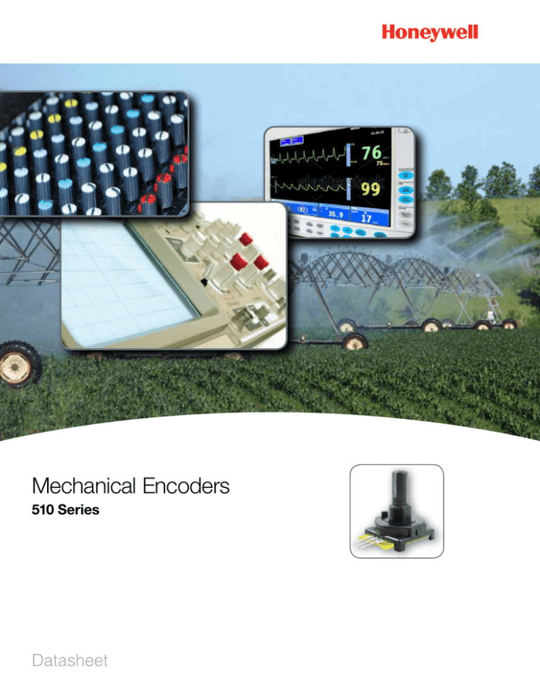
Mechanical Encoders
510 Series
Datasheet
510 Series Mechanical Encoders
The 510 Series are manually operated, rotary encoders that supply a 2-bit gray code output for relative reference
applications or a four-bit gray code output for absolute electrical reference applications. They combine the feel of a rotary
switch with a digital output.
The “L” channel leads the “R” channel by 90º electrically in the clockwise position. This series has continuous electrical
travel and has a rotational life of more than 100,000 shaft rotations with a positive detent feel.
These small encoders are commonly used in limited-space, panel-mounted applications where the need for costly, frontpanel displays can be completely eliminated. Digital gray code outputs may eliminate the need for analog/digital converters.
Key Features and Benefits
Potential Applications
•
High resolution: Up to 36 positions for applications that
INDUSTRIAL
require high resolution
•
Audio/visual equipment
Gray code digital voltage output: May eliminate the need
for analog to digital converters, contributes to a more costeffective solution
•
Smoke detectors
•
Irrigation controls
•
Oscilloscopes
Wide operating temperature range of -40 °C to 105 °C
•
Robotics
•
•
[-40 °F to 221 °F]: Helps minimize thermal performance
•
issues
MEDICAL
Mounting flexibility: Horizontal or vertical mounting
•
EKG and defibrillation machines
terminations promote flexibility in the application
high resolution • Gray Code Digital Output
2
sensing.honeywell.com
Mechanical Encoders
Table 1. Electrical Specifications
Parameter
Termination B
3 Leads
Termination B
5 Leads
Termination C
3 Leads
Termination C
5 Leads
2-bit gray code,
channel L leads
channel R by 90º
electrically CW
4-bit gray code,
absolute electrical
position output
2-bit gray code,
channel L leads
channel R by 90º
electrically CW
4-bit gray code,
absolute electrical
position output
Termination D
Characteristic
Output
Closed circuit resistance
2-bit gray code,
channel L leads
channel R by 90º
electrically CW
5 Ohm max.
Open circuit resistance
100 kOhm min.
Contact rating
250 mA at 28 Vdc max.
Switching loads:
14 Vdc
115 Vac
150 mA
1.5 mA
Dielectric
1000 Vac at sea level
Rotational life
100,000 cycles at rated load, typ.
Electrical travel
360º/continuous
Table 2. Mechanical Specifications
Parameter
Characteristic
Termination B
2-bit
Termination B
4-bit
Mechanical travel
Detent positions
Termination C
2-bit
Termination C
4-bit
Termination D
16
16
360º/continuous
16
16, 24, or 361
16, 24, or 361
Operating torque
21 mN m to 23 mN m [3 in-oz to 5 in-oz]
Operating speed
50 rpm, max.
Termination type
formed, C-30 type
formed, C-30 type
with mounting bracket
straight, B-110 type
Material:
housing, bushing, shaft
terminals
PCB
glass-reinforced thermoplastic
tin-plated brass
FR4
See Order Guide Tables on pp. 5-7.
1
Table 3. Environmental Specifications
Parameter
Characteristic
Termination B
2-bit
Termination B
4-bit
Termination C
2-bit
Termination C
4-bit
Operating temperature
-40 ºC to 105 ºC [-40 ºF to 221 ºF]
Storage temperature
-55 ºC to 120 ºC [-67 ºF to 248 ºF]
Sealing
Termination D
Controls are not sealed for board washing. Consult Honeywell for details.
sensing.honeywell.com
3
510 Series
Figure 1. Output Information
Incremental Output Graphs (Clockwise Rotation)
1 = 20
Position 1 G 2
G = Ground
1
2 = 21
2
3
Closed
4
Open
5
6
7
8
9
10
11
12
13
14
2-bit,
15
16 detent
16
17
18
19
20
21
22
2-bit,
23
24 detent
24
25
26
27
28
29
30
31
32
33
34
2-bit,
35
36 detent
36
Channel Graph
1
R
0
1
Position 1 4 2 G 8
1 = 20
4 = 22
1
2
2 = 21
3
G = Ground
4
8 = 23
5
Closed
6
Open
7
8
9
10
11
12
13
14
15
4-bit,
16
16 detent
L
0
CW
¼ Cycle per detent
510 Series Mechanical Encoder
Product Nomenclature
Figure 2. Nomenclature Tree
For example, 5101A48F204PB defines a 510 Series Mechanical Encoder, anti-rotation locating pin at the 9 o’ clock position, 3/8-32 UNEF-2A,
9,53 mm [0.25 in] bushing type and length, 19,05 mm [0.750 in] shaft length, flatted shaft, 2-bit: 4 cycles per revolution, 16 detents per revolution,
PC type B-110 termination.
510
Series
510 Series
Mechanical
Encoder
A
48
Bushing
Type and Length
Shaft Length
(From Mounting
Surface)
1
Anti-Rotation
Locating Pin
1 at 9 o’ clock
A
3/8-32 UNEF-2A
6,35 mm [0.25 in]
48
19,05 mm
[0.750 in]
F
204P
B
Shaft
Type
Bits, Cycles, and Mechanical
Detents per Revolution
(Gray Code Options)
Termination
Type
1 Flatted
PC type B-110
2-bit: 4 cycles per revolution,
B (straight for horizontal mount)
2-bit: 6 cycles per revolution,
C PC type C-30
204P 16 detents per revolution
206P 24 detents per revolution
2-bit: 9 cycles per revolution,
209P 36 detents per revolution
(bent for vertical mount)
PC type C-30
D (bent for vertical mount) with
mounting bracket
416P 4-bit: 16 cycles per revolution,
16 detents per revolution
4
sensing.honeywell.com
005965-1-EN
Mechanical Encoders
Table 510-A Order Guide
Electrical
Mechanical
Number of Bits
Detent Positions
510E1A48F204PB
2
510E1A48F206PB
510E1A48F209PB
Catalog Listing
RoHS Compliant
Mounting Hardware
16
yes
none
2
24
yes
none
2
36
yes
none
Dimensional Drawing (For reference only: mm [in].)
Shown with shaft in position 1
21,08
[0.830]
8,13
[0.320]
19,1
[0.752]
8,71
[0.343]
6,35
[0.250]
9,53
[0.375]
ø6,27
[0.247]
21,08
[0.830]
5,54
[0.218]
15,62
[0.615]
3/8-32 UNEF-2A
Mounting surface
90°
6,35
[0.250]
2X 2,54
[0.100]
Table 510-B Order Guide
Catalog Listing
510E1A48F416PB
Electrical
Mechanical
Number of Bits
Detent Positions
4
16
RoHS Compliant
Mounting Hardware
yes
none
Dimensional Drawing (For reference only: mm [in].)
Shown with shaft in position 1
21,08
[0.830]
8,13
[0.320]
19,1
[0.752]
ø6,27
[0.247]
8,71
[0.343]
6,35
[0.250]
9,53
[0.375]
21,08
[0.830]
5,54
[0.218]
15,62
[0.615]
3/8-32 UNEF-2A
Mounting surface
90°
8,13
[0.320]
2X 2,54
[0.100]
sensing.honeywell.com
5
510 Series
Table 510-C Order Guide
Electrical
Mechanical
Number of Bits
Detent Positions
510E1A48F204PC
2
510E1A48F206PC
510E1A48F209PC
Catalog Listing
RoHS Compliant
Mounting Hardware
16
yes
none
2
24
yes
none
2
36
yes
none
Dimensional Drawing (For reference only: mm [in].)
Shown with shaft in position 1
19,1
[0.752]
6,35
[0.250]
21,08
[0.830]
8,1
[0.32]
ø6,27
8,71
[0.343]
9,53
[0.375]
[0.247]
21,08
[0.830]
90°
5,54
[0.218] 3/8-32 UNEF-2A
Mounting surface
15,62
[0.615]
3,97, Typ.
[0.156]
2X 2,54
[0.100]
Table 510-D Order Guide
Catalog Listing
510E1A48F416PC
Electrical
Mechanical
Number of Bits
Detent Positions
4
16
RoHS Compliant
Mounting Hardware
yes
none
Dimensional Drawing (For reference only: mm [in].)
Shown with shaft in position 1
21,08
[0.830]
8,13
[0.320]
19,1
[0.752]
6,35
[0.250]
ø6,27
[0.247]
8,71
[0.343]
9,53
[0.375]
21,08
[0.830]
5,54
[0.218]
90°
3/8-32 UNEF-2A
Mounting surface
3,97
[0.156]
15,62
[0.615]
2X 2,54
[0.100]
6
sensing.honeywell.com
Mechanical Encoders
Table 510-E Order Guide
Catalog Listing
510E1A48F209PC
Electrical
Mechanical
Number of Bits
Detent Positions
2
36
RoHS Compliant
Mounting Hardware
yes
mounting bracket
Dimensional Drawing (For reference only: mm [in].)
Shown with shaft in position 1
21,08
[0.830]
8,13
[0.320]
18,59
[0.732]
ø6,27
5,84
[0.230]
9,22
[0.363]
3.73
[0.147]
[0.247]
21,08
[0.830]
15,32
[0.603]
5,54
[0.218]
90°
3/8-32 UNEF-2A
Mounting surface
15,62
[0.615]
15,88
[0.625]
2X 2,54
[0.100]
Figure 3. 510BKT Mounting Bracket (available separately)
sensing.honeywell.com
7
ADDITIONAL INFORMATION
The following associated literature is available at sensing.honeywell.com:
• Product Range Guide
• Product Line Guide
• Installation Instructions
WARNING
PERSONAL INJURY
DO NOT USE these products as safety or emergency stop
devices or in any other application where failure of the product
could result in personal injury.
Failure to comply with these instructions could result in
death or serious injury.
WARNING
MISUSE OF DOCUMENTATION
•
•
The information presented in this product sheet is for
reference only. Do not use this document as a product
installation guide.
Complete installation, operation, and maintenance
information is provided in the instructions supplied with
each product.
Failure to comply with these instructions could result in
death or serious injury.
WARRANTY/REMEDY
Find out more
Honeywell serves its customers
through a worldwide network
of sales offices, representatives
and distributors. For application
assistance, current specifications,
pricing or name of the nearest
Authorized Distributor, contact
your local sales office.
To learn more about Honeywell’s
Honeywell warrants goods of its manufacture as being free of
defective materials and faulty workmanship. Honeywell’s standard
product warranty applies unless agreed to otherwise by Honeywell
in writing; please refer to your order acknowledgement or consult
your local sales office for specific warranty details. If warranted
goods are returned to Honeywell during the period of coverage,
Honeywell will repair or replace, at its option, without charge
those items it finds defective. The foregoing is buyer’s sole
remedy and is in lieu of all other warranties, expressed or
implied, including those of merchantability and fitness for
a particular purpose. In no event shall Honeywell be liable
for consequential, special, or indirect damages.
While we provide application assistance personally, through our
literature and the Honeywell website, it is up to the customer to
determine the suitability of the product in the application.
Specifications may change without notice. The information we
supply is believed to be accurate and reliable as of this printing.
However, we assume no responsibility for its use.
sensing and control products,
call +1-815-235-6847 or
1-800-537-6945,
visit sensing.honeywell.com,
or e-mail inquiries to
info.sc@honeywell.com
Sensing and Control
Honeywell
1985 Douglas Drive North
Golden Valley, MN 55422
honeywell.com
32301267-A-EN IL50
October 2014
© 2014 Honeywell International Inc. All rights reserved.


