BLS3000 Datasheet
advertisement

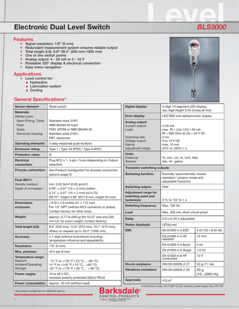
Level Electronic Dual Level Switch BLS3000 Features Signal resolution: 1/5" (5 mm) Redundant measurement system ensures reliable output Total length (L0): 9.8"-39.4" (250 mm-1000 mm) One or two switch points Analog output: 4 - 20 mA or 0 - 10 V Rotatable 320° display & electrical connection Easy menu navigation Applications Level control for: l Hydraulics l Lubrication system l Cooling General Specifications* Sensor element: Materials: Wetted parts: Stem (Fitting, Tube): Float: Seals: Electronic housing: Reed switch Stainless steel 316Ti NBR (BUNA-N) foam FKM, EPDM or NBR (BUNA-N) Stainless steel 316Ti, PBT, elastomer Operating elements: 3 easy-response push-buttons Enclosure rating: Type 1 / Type 4X (IP65) / Type 6 (IP67) Protection class: III Electrical connection: Plug M12 x 1, 4-pin / 5-pin (depending on Output selection) Process connection: See Product Configurator for process connection options (page 2) Float BN17: Density medium: Depth of immersion: min. 0.02 lb/in³ (0.60 g/cm³) 0.59” ± 0.07” (15 ± 2 mm) (water) 0.74” ± 0.07” (19 ± 2 mm) (oil 0.75) Ø0.70”, height 0.98” (Ø17.8 mm, height 25 mm) Digital display: 4-digit 14-segment LED display, red, digit height 0.35 inches (9 mm) Error display: LED RED and alphanumeric display Analog output: Current output: Load: Scanning rate: Voltage output: Rating: Adjustment range: 4-20 mA max. RI = (Ub-12V) / 20 mA RI = 600 Ohm at Ub = 24 V DC 2 ms 0 to 10 V DC max. 10 mA 25% to 100% f. s. Units: Distance: Volume: %, mm, cm, m, inch, feet, liter, m³, gallon Transistor switchting outputs: Switching function: Normally open/normally closed, standard / window mode and adjustable functions Switching output: PNP Adjustment range for switching point and hysteresis: 0 % to 125 % f. s. Switching frequency: Max. 100 Hz Dimensions enclosure: 1.6 Ø x 4.5 inches (41 x 115 mm) For 1/2" NPT (without M12 connector or probe). Contact factory for other sizes. Load Max. 500 mA, short-circuit proof Weight: Approx. 0.77 lb (350 g) (for G1/2” size and 250 mm L0, for exact weight, contact factory) Delay 0.0 s to 50 s adjustable Total lenght (L0): 9.8" (250 mm), 14.6" (370 mm), 16.1" (410 mm), others on request up to 39.4” (1000 mm) Status display(s): LED(s) red EMI: EN 61000-4-2 ESD 4 kV CD / 8 kV AD Accuracy: ± 1 digit (without turbulence) including temperature influence and repeatability EN 61000-4-3 HF radiated 10 V/m Resolution: 1/5" (5 mm) EN 61000-4-4 Burst 2 kV Max. pressure: 43.5 psi (3 bar) EN 61000-4-5-Surge 1/2 kV EN 61000-4-6 HF conducted 10 V Temperature range: Medium: Ambient/Operating: Storage: -13 °F to +176 °F (-25 °C... +80 °C) 14 °F to +140 °F (-10 °C... +60 °C) -22 °F to +176 °F (-30 °C… + 80 °C) Power supply: 15 to 28 V DC, reversed polarity protected (SELV, PELV) Power consumption: Approx. 50 mA (without load) * See product configurator for additional options. 1 Shock resistance DIN EN 60028-2-27 50 g (11 ms) Vibrations resistance DIN EN 60028-2-26 20 g (10...2000 Hz) Approvals: cULus1 1) Conditions of use: 140 °F (60 °C) max. ambient, power supply max. 28 V DC 4 4 3 Pressure Pressure Pressure 2 2 3 Electr. Dual Pressure Switch Electr. Dual Pressure Electr. Dual Switch Pressure Switch BPS3000 BPS3000 BPS3000 Dimensions (mm / inch) Dimensions (mm / inch)Dimensions (mm / inch) Electronic Dual Level Switch D G 1/2" BLS3000 G 1/2" D Technical Drawings Electrical Connection Chart Models with 4Models with C 1/2" NPT SHOWN 3 X X X -XXXXX BPS 3 BPS X 3X X X 0…x PSI Gauge Pressure XXXXP Sealing H B B B PROCESS CONNECTION . Sealing SP1 SP1 (500 mA/100 Hz) (500 mA/100 Hz) 2 G1/2" 2 G1/2" Flush Diaphr.Flush Diaphr. 4 5 5 40x40 Cetop 40x40 Cetop 6 7/16-20 UNF Ext. Threat 6 UNF Ext. Threat 7/16-206UNF7/16-20 Ext. Threat 1 . . Pin 5 Gray Length . . 3 Ext.1/4"NPT 1/4"NPT Threat Ext. Threat Not1/2"NPT Applicable Not Applicable 4 Flush 1/2"NPT Diaphr.Flush Diaphr. . . C . . . . 2 Switch Points 2 4…20mA 1 Switch Points 3 0…10V 1 Switch Points 4 4…20mA 2 Switch Points 4 4 2 Switch 4…20mA 2 Switch Points 4…20mA Points 5 0…10V 2 Switch Points 5 0…10V 2 Switch Points 0…10V52 Switch Points . . . . . . SP2 (500 mA/100 Hz) . Output OutputNPT, 1/2” 3/4” NPT, 1 Points 2 Switch Points 1 Switch 1”24…20mA NPT, 1 1/4” NPT, 2 1 Switch 4…20mA 1 Switch Points 2 Points 7/8-SAE 10, 1-1/16-12 SAE 12 31 Switch 0…10V 1 Switch Points 3 0…10V Points . G1/2”, G 3/4”, G1”, M20X1.5 . . . . 9.8” 250 mm . L0 PROCESS CONNECTION 14.6” 370 mm 16.1” 2 Subject to technical changes. I PROCESS CONNECTION L0 = Total Length for G & M & SAE Threads C 1.16 29.40 1.26 32 1.18 30 L0 = Total Length for NPT Threads .55 14 .63 16 LM =GL0 - (To + Tu) 1/2 " G 3/4" To = Top Dead Band Tu = Bottom Dead Band 410 mm Dead band 1.16 29.40 Process Connection technical changes.Barksdale Subject to Subject technicaltochanges. To (Top) .55 14 2 2 D SP1 (500 mA/100 Hz) 1 Threat G1/4" Ext. Threat G1/4" Ext. 1 . 0V EPDM Process Connection Process Connection G1/4" Ext. Threat Output Analog Output 4-20 mA/0-10 V 0V FKM 3 . REV. M20 X 1.5 . 40x40 Cetop . A.1 F G H I . 1/2"NPT Flush Diaphr. .69 17.40 E EPDM 2 . 1/4"NPT Ext. Threat . F FKM 2 5 . G 1 1 4 D F 0V Sealing 3 . G XXXXP0…x PSI Gauge 0…xPressure PSI Gauge Pressure 2 . 3 15 to 28 1 VDC 15 to 28 VDC Pin 4 Black G1/2" Flush Diaphr. . H 15 to 228 VDC SP2 Range Analog Output Range (500 mA/100 Hz) 4-20 mA/0-10 V XXXXb0…x bar Gauge 0…xPressure bar Gauge Pressure Pin 3 Blue Process Connection 1 . .55 14 Process Connections* EPDM . I C FKM 2 . 1 E =LO LENGTH FOR E =LO LENGTH FOR NON-NPT THREADS NON-NPT THREADS F =LO LENGTH FOR F =LO LENGTH FOR NPT THREADS NPT THREADS C 17 MM FLOAT 17 MM FLOAT .69 17.40 1 . 2 -XXXXX 0…x bar Gauge Pressure XXXXb XXXXP 3 D Pin 2 White XXXXb 3 D X-XXXXX X Range C 1/2" NPT SHOWN G1/2” M20 X 1.5 G3/4” G1” B M20 x 1.5 mm 1/2” NPT 1.46 37 3/4” NPT 1” NPT .71 18 1¼” NPT G 1" 7/8-14 UNF (SAE 10) 1/2 " NPT 1 1/16-2 UN (SAE 12) C .55 14 1.06 ± 0.12 [27 ± 3] 1.14 ± 0.12 [29G 1/2 ± "3] 1.22 ± 0.12 [31 ± 3] 1.06 ± 0.12 [27 ± 3] .63 16 G 3/4" 1.06 ± 0.12 [27± 3] 1.18 30 1.18 30 0.51 ± 0.12 [13 ± 3] 1.59 4 .79 20.14 .78 19.90 1.26 1.18 30 Barksdale Barksdale Tu (Buttom) .98 25 1.01 ± 0.12 [25.7 ± 3] 3/4" NPT 1.1 ± 0.12 [28 ± 3] 1" NPT G1/2", G 3/4", G1", M20X1,5 E L0 = Total Length for G & M & SAE Threads 1.18 30 1.22 30.886 1.18 30 1.59 40.40 1.59 40.40 1/2" NPT, 3/4" NPT, 1.06 27.01 7/8-16 (SAE#10), 1 1/16-12 G1/2", G 3/4", G1", M20X1,5 1.26 1.18 30Length for G & L0 = Total M32& SAE Threads 1.46 37 LENGTH A NPT, 1 1/4" NPT.50 12.70 1" (SAE#12) 1/2" NPT, 3/4" 20.14 1.00 NPT, 25.50 7/8-16.79(SAE#10), 1 1/16-12 .78 19.90 .47 11.91 .55 14 .98 25 LENGTH F L0.63=16Total Length for NPT Threads .71 18 1" NPT, 1 1/4" NPT (SAE#12) F G 1/2 " L0 = TotalGLength for NPT Threads M20 X 1.5 1 1/16-12 (SAE#12 ORB) 3/4" 3/4" NPT 1/2 " NPT 9.8 IN [250 MM] 1 1/4" NPT 9.8 IN [ 7/8-14 250 (SAE#10 MM]ORB) G LM = L0G-1"(To + Tu) 1" NPT Dimensions inches [mm] 9.8 IN [250 MM] * Non NPT fittings are shown without seals B 9.8 IN [ 250 MM] G LM = L0 - (To + Tu) 14.6 IN [370 MM] 14.6 IN [370 MM] LO H To = Top Dead Band 14.6 IN [370 MM] 14.6 IN [370 MM] LO 1.22 30.886 16.1 IN [410 MM] 3 16.1 IN [410 MM]4 H To = Top Dead Band Example BLS3 1 1.06 27.016 X IN [410 M 14.6Z 1.18 30 1.18 30 1.59 40.40 1.59 40.40 16.1 MM] 16.1 IN [410 MM] A .50 12.70 I Tu = Bottom Dead Band .47 11.91 .79 20.14 1.00 25.50 I Tu = Bottom .98 Dead Band Series:.78 19.90 25 3 E C DWG. BLS3000 1.16 29.40 .55 14 Product Configurator 7/8-14 (SAE#10 ORB) Total Sensor Length L0 : 1 1/16-12 (SAE#12 ORB) WEIGHT SCALE DWG. A NPT BLS3000 Series 3/4" BLS3000, electronic dual level switch 1 1/4" NPT A.1 XXX C NPT 5. DIMENSIONS 1"ARE IN INCHES.DIMENSIONS IN [] ARE IN MILLIMETERS AND FOR REFERENCE ONLY 250 mm (process con. code 2, 5, A & H) 0250M4 5. DIMENSIONS ARE IN INCHES.DIMENSIONS IN [] ARE IN MILLIMETERS AND FOR REFERENCE ONLY 4 3 2 1 Output: 1.06 27.01 1.22 30.886 370 mm (process con. code 2, 5, A & H) 4. ELECTRICAL CONNECTION & DISPLAY CAN BE ROTATED 320 INDEPENDENTLY 0370M4 12.70 ELECTRICAL CONNECTION & DISPLAY CAN BE ROTATED 320 INDEPENDENTLY 1 4. .50Dual switch point .47 11.91 A 4 410DRAWN mm (process 0410M 3 MATING CONNECTORS ( 4 PINS P/N 239537, 5 PINS P/N 239263) OR CABLE ASSEMBLIES (4PINS DATEcon. code 2, 5, A & H) 7/8-14 ORB) 1 1/16-12 (SAE#12 ORB) plus 4-20mA 2(SAE#10 switch point 03-07-2016 HTRAN 3 Single MATING CONNECTORS ( 4 PINS P/N 239537, PINS P/N 239263) ORPROVIDED CABLE ASSEMBLIES DRAWN DATE P/N 239535-XX) AND 5 PINS P/N5239546-XX) ARE NOT WITH UNIT.(4PINS ELECTRONIC LEVEL SW BLS3000 5 03-07-2016 HTRAN A.1 XXX C 9.8CHECKED inch (process DATEcon. code 3, 6, B, C, I, & J) 09.8Z P/N switch 239535-XX) AND 5 AVAILABLE PINS P/N 239546-XX) ARE NOT PROVIDED WITH UNIT. ELECTRONIC LEVEL SWITCH THEY ARE0-10V AS ACCESSORIES 3 Single point plus XX-XX-XX BLS3000 XXX CHECKED DATE 4 THEY ARE AVAILABLE AS ACCESSORIES 3 2 1 XX-XX-XX BLS3000 XXX 5 APPROVED DATE con. code 14.6 inch (process 3, 6, B, C, I, & J) 14.6Z 4 Dual switch plus 4-20mA 2.point WHEN ORDERING REFER TO SWITCH CONFIGURATOR IN PAGE 2 TO OBTAIN CORRECT SWITCH XXX XX-XX-XX APPROVED DATE 2. WHEN ORDERING REFER TO SWITCH CONFIGURATOR IN PAGE 2 TO OBTAIN CORRECT SWITCH XXX XX-XX-XX UNLESS OTHERWISE 5 16.1 inch (process con. code 3, 6, B, C, I, & J) 5 Dual switch point plus 0-10V 16.1Z SPECIFIED UNLESS OTHERWISE 1. SWITCH IS UL AND CSA APPROVED DIMENSIONAL TOLERANCES SPECIFIED 1. SWITCH IS UL AND CSA APPROVED DIMENSIONAL TOLERANCES FRACTIONAL ±1/16 Process Connections: DECIMAL ±.010 www.bark Electrical Connection: ANGULAR ± 5° FRACTIONAL ±1/16 NOTES: UNLESS OTHERWISE SPECIFIED DECIMAL ±.010 ANGULAR ± 5° DIMENSIONS IN BOXES NOTES: UNLESS OTHERWISE SPECIFIED 2 G1/2” male, with seal (seal code V, E or B) ARE IN MILLIMETERS Ph:90 3 Los Angeles, CA IN BOXES M12 xDIMENSIONS 1 mm (4 or 5 pin) M2 ARE IN MILLIMETERS Ph: 323-589-6181 Fax: 323Seal Material: 3 1/2” NPT male, without seal (seal code X) BLS3 1/2 " NPT REV. SHEET A B SIZE B Order Code Order Code Order Code BPS Pin 1 Brown REV. 1.06 [27] HEX 1.06 [27] HEX 3.35 [85] A.1 4 D 3.35 [85] Plug 4-pin Color Code of Mating Cable BLS3000 4 M12 X 1 CONNECTOR M12 X 1 CONNECTOR Mating connector not included; see .71 18 accesories for .71 18 options Models with 1 switching Plug Plug2 switching output and output and 1 analog Plug 4-pin 1 analog Plug 5-pin output output 2 switching Plug output C M12 Pin Connection diagram Connection diagram Connection diagram Call-Out DWG. G 1/2" SIZE 1.6 40.6 1.6 40.6 WEIGHT A A DWG. SCALE REV. SHEET 4 4 OF 3 5 G3/4” male, with seal (seal code V, E or B) X 3 No seal is required for NPT thread 6 3/4” NPT male, without seal (seal code X) V FKM (fluoroelastomer) A G1” male, with seal (seal code V, E or B) E EPDM (EPR) B NBR (BUNA-N) B 1” NPT male, without seal (seal code X) C 1¼” NPT male, without seal (seal code X) H M20 x 1.5 mm male, with seal (seal code V, E or B) I 7/8-14 UNF (SAE 10) male, (seal code V, E or B) 1 J1 1 1/16 -12 UN (SAE 12) male, (seal code V, E or B) Note: 1. Subject to minimum order quantity of 10 pieces; consult factory for lead time. 2. Mating connector not included with unit; mating connectors are available and can be ordered as an accessory. 3. Custom length available up to 39.4” (1000mm); minimum quantities may apply. 4. Available only for G & M thread. 5. Available only for NPT, UNF & UN thread. 6. See Cable Connectors & Accessories for more options. OF 2 2 Accessories Order Number Description 239535-1M-R-S6 4 Pin M12 Female Right Angle Plug Molded Cable, 3.28 Feet (1 Meter), Shielded 239535-1M-S6 239537 239236 239546-1M-R-S6 239546-1M-S6 239548-S 239548-R 4 Pin M12 Female Straight Plug Molded Cable, 3.28 Feet (1 Meter), Shielded 4 Pin M12 Female Straight Connector 4 Pin M12 Female Right Angle Connector 5 Pin M12 Female Right Angle Molded Cable, 3.28 Feet (1 Meter), Shielded 5 Pin M12, Female Straight Plug Molded Cable, 3.28 Feet (1 Meter), Shielded 5 Pin M12 Female Straight Connector 5 Pin M12 Female Right Angle Connector 3211 Fruitland Avenue • Los Angeles, CA 90058 • % 800-835-1060 • Fax: 323-589-3463 • www.barksdale.com See Barksdale’s Standard Conditions of Sale • Specifications are subject to modification at any time • Bulletin #L0043-A • 04/16 • ©2016 • Printed in the U.S.A. 2


