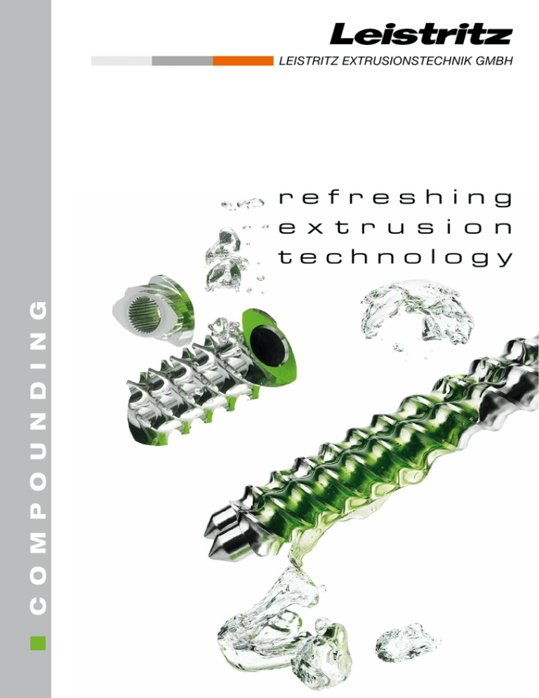
Leistritz compounding brochure
advertisement

LEISTRITZ EXTRUSIONSTECHNIK GMBH C O M P O U N D I N G refreshing e x t r u s i o n technology Process Filling (e.g. CaCO3, wood compound) Reinforcing (e.g. fibre) Raw polymer Employing additives (e.g. flame retardants, UV stabilizers) Crosslinking of elastomers (e.g. TPE-V) Reactive extrusion Blending (e.g. Polycarbonate + ABS) Compounding… … is a process, in which polymer are melted and mixed with e.g. additives, fillers or reinforcing materials. This process changes the physical, thermal, electrical or aesthetic characteristics (conductivity, flame resistance, wear resistance, structural behaviour, colours…) of the polymer. The end product is called compound or composite. The compounding of thermoplastics is one of the main application areas of Leistritz twin screw extruders. Like listed above, the excellent incorporation characteristics of additives, fillers and reinforcing materials into the polymer matrix create products that are used in numerous fields of application. 2 A P P L I C AT I O N Process End product e.g. computer housing e.g. car frontend e.g. garden furniture e.g. tool handles e.g. shoe soles, ski boots e.g. headlamp housings for cars Compounding examples: reinforcement of polymers, e.g. by incorporating glass, carbon or natural fibres) modification of the impact strength of thermoplastics, e.g. by blending them with rubber components enhancement of the dimensional stability and breaking resistance of polymers, e.g. by incorporating inorganic fillers, glass beads improvement of the flow behaviour and the flame resistance of polymers, e.g. by incorporating low- viscosity substances or flame retardants production of polymer blends, e.g. by mixing compatible and incompatible polymers enhancement of the chemical/physical durability of polymers, e.g. by incorporating stabilizers, static inhibitors A P P L I C AT I O N 3 Filling Fillers are incorporated into the polymer matrix in order to improve the polymer properties or/and to reduce the price of the compound. The good feasibility of incorporating fillers into the polymer matrix are used in a variety of applications (production of e.g. computer housing). Another example: drain pipes. In this case, fillers are used for sound insulation (practical reason: reduction of flushing sounds in an apartment building). Leistritz extruders are able to incorporate large amounts of fillers (e.g. filler masterbatch). Here, the polymer can be blended with more than 80% of fillers such as chalk and talcum. The predominant compounding requirement is to incorporate as much filler material as possible. The main challenge here is to disperse the fillers in an optimum way. The dispersion process can be divided into the following steps: melting of the matrix wetting of the filler material distribution in the matrix homogenizing and degassing of the melt Side feeders are used for adding fillers. When working with a high share of fillers two or three can be applied. In this case, the modular processing unit of the extruder is just being extended. Depending on the formulation, the material stream of the feed material is divided into the existing feed openings. This is done in order to minimize abrasion and to wet the fillers as good as possible. Frequently used fillers Example of a ZSE 50 MAXX with two side feeders 4 A P P L I C AT I O N Talcum is flaky: primarily fed into the melt via a side feeder. Calcium carbonate is spherical or cubical: can also be fed via the main feed port. It is available in three forms: chalk, lime stone or marble. Filling Application Example: 13 - 20% PP + 80 - 87% CaCO3 Screw Geometry: Line Layout: fillers, gravimetric feeder fillers, gravimetric feeder polymer (+ possibly filler material) side feeder degassing vent side feeder vent gravimetric feeder granulator ZSE MAXX Test Results: ZSE 50 HP vs. ZSE 50 MAXX PP + 80% CaCO3 ZSE 50 HP ZSE 50 MAXX OD/ID = 1.66 torque density of up to 15.0 Nm/cm3 1000 900 throughput (kg/h) ZSE MAXX extruders are state-of-the-art machines which have the optimum ratio of torque and volume: 800 Predecessor model ZSE HP: 700 OD/ID = 1.5 torque density of up to 10.5 Nm/cm3 600 500 400 300 300 600 900 screw speed (U/min) A P P L I C AT I O N 5 Reinforcement Especially in applications where parameters such as tensile strength or impact resistance are relevant, the polymer (e.g. PP or PE) is reinforced with materials like glass fibres, carbon fibres or even natural fibres. The filling degree of e.g. PP with glass fibres can amount to 60%, if necessary. When the polymer chains agglomerate and link to the fibre structure, an unbreakable and impact resistant connection develops – a connection that matches the mechanical properties of metallic materials. Because of the low weight of reinforced thermoplastic polymers, they are in great demand, especially in the automotive industry. Glass Fibres, Glass Beads The aim when working with glass fibres or beads in twin screw extruders is to distribute them homogeneously in the polymer matrix, to obtain an optimum lengthwise distribution in the end product without destroying them. Generally, chopped or short glass fibres with an initial length of up to approximately 3 mm is used. Long fibres can have a length of 25 to 30 mm in the product. Long fibres Short fibres better mechanical product properties, poor flow behaviour in the melt (e.g. when processed further in the injection molding step) poor mechanical product properties, better mold filling character- istics in the injection molding step Processing in a Twin Screw Extruder When incorporating glass fibres into the polymer matrix, it is important not to damage or even to evaporate the fibre´s sizing (serves to compensate the surface tension) by turning the temperature too high. The sizing has to be compatible to the polymer matrix. Therefore, the fibre is normally fed into the melt after the plasticizing step. If it was added via the main port, the fibres would be chopped too much in the plasticizing unit and it would result in too much abrasion in the melting zone. REM picture: glass fibres, well embedded in a PC matrix Source: Georg-Simon-Ohm-University of Applied Sciences 6 A P P L I C AT I O N Reinforcement Application Example: Incorporation of Glass Fibres (40%) in Polycarbonate (60%) Screw Geometry: Line Layout: gravimetric feeder (glass fibres) raw polymer side feeder Gravimetrische Dosierung degassing vent granulator ZSE MAXX water bath Test Results: ZSE 50 MAXX vs. ZSE 50 HP ZSE 50 HP vs. ZSE 50 MAXX ZSE 50 HP PC+GF 40% throughput (kg/h) ZSE 50 MAXX PC+GF 40% PC + 40% GF Results: A ZSE MAXX extruder is the ultimate choice for running shear-sensitive applications. An increase of throughput of up to 55% can be realized here. Due to the high free volume (OD/ID = 1.66) and the high torque (up to 15 Nm/cm³) energy savings of up to 18% can be achieved. screw speed (U/min) A P P L I C AT I O N 7 Special Applications Special compounds use polymers that are developed for extraordinary demands. Those polymers are technical thermoplastic polymers like for example PA 6, PA66, PA 12 (Polyamides), PPA (Polyphtalamides), PSU (Polysulfones), PEEK (Polyetheretherketones), PBT (Polybutylene terephthalates), POM (Polyoxymethylen) or PPS (Polyphenol sulfides). This functionality of polymers is improved by according additives. Thereby, the product gets special properties, e.g.: materials which are tribologically optimized by PTFE (Polytetrafluoroethylene), aramides, carbon fibres, PFPE (Perfluoropolyether), special lubrication systems conductive materials (antistatic, EMV shield) by permanent antistatic, conductive carbon black, carbon fibres, stainless steel fibres, carbon nano tubes further additives for improving mold release, flow behaviour, heat conductivity, UV stabilization, fire behaviour, flame retardance, surface feel, water absorption, impact strength etc. metall compounds on the basis of e.g. PPS (Polyphenylensulfid) for injection molding: end product: e.g. ring magnet for electric motors (see picture below) Example: Production of TPE-V The production of TPE-V is considered to be quite problematic, because of the rubber share which is to be fed into the extruder. An optimum solution is an extruder/gear pump combination. One part is a ZSE MAXX extruder (achieves up to 30% more throughput because of an OD/ID of 1.66 and a very high torque of up to 15.0 Nm/cm³), and the other is a special device for dosing feed strips. Most important processing advantages: By feeding already plasticized compounds with a high oil share (feeding strips, prebatch), the processing steps can be considerably reduced. With higher throughputs, lower mass temperatures and the usage of low-priced linking systems, much higher line productivity can be achieved. The investment sum for the overall machine and its amortization period are drastically reduced. Example of a ZSE 18 HPe for metal compounding with downstream equipment (air granulator, cooling and vibrator chute) 8 A P P L I C AT I O N Direct Extrusion Direct extrusion or inline-compounding can produce products in a more efficient manner by combining various process tasks in a single production line. The process has particular relevance since the pelletizing step can be left out and the compounder is also used for shaping the product. E.g. by using a die with according downstream equipment, films, sheets, pipes or injection molding parts can be produced. Advantages: The pelletizing step is eliminated. Due to a reduced melt temperature the process window is widened. The polymer is only once exposed to temperature and shear (there is no second energetic exposure). Valuable formulation know-how stays in-house. The process saves energy. With direct extrusion the materials have one less heat and shear history which often results in improved mechanical properties of the end product. Example: In-line PET processing with and without predrying for multi-layer films in a co-extrusion process PET process with predrying predryingcompounder pelletizingpredryingextrusionflat film The in-line process is in contrast to that: compounder flat film The pelletizing step as well as the second melting step and the predrying of the polymer are omitted. Drawing of a film extrusion line A P P L I C AT I O N 9 Additional Options Leistritz Side Feeder: LSB 50 XX A side feeder is mainly used for dosing powder. In order to transport the material safely into the process, twin screws are used – similar to the ones in the extruder. An important parameter of the LSB screws lies in the high OD/ID ratio. This facilitates feeding of material with low bulk density. With the LSB 50 XX Leistritz thought one step further. A specific feature of this side feeder is the possibility of using segmented screws. Similar to the extruder, the screws can be configured according to the material properties. This way it is possible to e.g. pre-compact the product and to remove air from the process. The adaption of the LSB to the extruder was also reconsidered. Now tie rods are used, which are placed at the cool, easily accessible back of the gear box. With them the LSB can be fixed to the extruder barrels – without any risk of injuries. Optimum handling is facilitated by the according barrels at the extruder, which were redesigned. Both screws and barrels can be manufactured from any existing material which is appropriate for the extruder. It is therefore possible to feed abrasive (e.g. TiO2) as well as highly corrosive products via the side feeder. Optionally, it is possible to cool the screws internally. This is done by means of a special gear construction: The drive shafts are designed as tubes. So the cooling agent can be transported into the screws via attached rotary feeders. Leistritz Side Degassing (LSE) Besides the commonly known processing steps like melting, mixing or homogenizing, degassing of volatile substances represents an important part of processing technology. The Leistritz Side Degassing is an alternative to conventional degassing systems which are mounted above the processing unit. The combination with a high free volume in the screw channel and the permanent renewal of the product surface create an optimum surrounding for degassing of the polymer melt. Though the screws, which are located in the degassing barrel, push the melt back into the processing chamber, gases can still escape. This way, plugging or deposits in the vacuum port can be avoided. Conventional degassing unit 10 F E AT U R E S LSE Side degassing unit 3D view of side degassing (LSE) ZSE MAXX Extruder The ZSE MAXX series offers maximum values for torque and volume in one system (OD/ID = 1.66). By an optimized volume/torque ratio the throughputs increase significantly by up to 50 %. This is made possible by a splined shaft design - maXXshaft – that opens up great potentials. The design allows for deeper screw channels at highest torques so that the free volume in the processing unit is increased by up to 30%. Consequently, maXXvolume is available for volume restricted processes. Ratio of outer screw diameter to inner screw diameter: OD/ID = 1.66 The specific torque for the ZSE MAXX series is: 15.0 Nm/cm³ (called maXXtorque). Due to the increased throughput/energy ratio, the cooling capacity also had to be increased. With maXXcooling up to 30% more cooling capacity is achieved by a sophisticated flow of cooling agent. The modular barrel and screw system can be fully utilized due to a flexible machine design. 50% increase of throughput by means of: maXXvolume Increased free volume in the screw (OD/ID = 1.66) maXXshaft Very high total torque by new splined shaft design maXXcooling Up to 30% increased barrel cooling capacity by means of optimized flow of the liquid coolant through the barrel cooling bores maXXtorque Very high available specific torque with co-rotating twin screw extruders (up to 15.0 Nm/cm3) Increased screw volume at the same centreline distance like the ZSE HP series (orange = increase in volume) Shaft profile with significant potential for the future Optimized barrel cooling system with maintenance-free high-end valves Extremely reliable and powerful co-rotating extruder gear box T E C H N O L O G Y 11 LEISTRITZ GROUP LEISTRITZ TURBOMASCHINEN TECHNIK GMBH Turbine and Compressor Blades LEISTRITZ PUMPEN GMBH Screw Pumps and Systems LEISTRITZ EXTRUSIONSTECHNIK GMBH Extruders and Extrusion Lines LEISTRITZ PRODUKTIONSTECHNIK GMBH Tubing Technology/Sheet Metal Forming, Machine Tools, Tools Partner for Modern Technology LEISTRITZ EXTRUSIONSTECHNIK GMBH Markgrafenstr. 29-39 . D-90459 Nürnberg LEISTRITZ Machinery (Taicang) Co., Ltd. Shanghai Branch Leistritz Advanced Technologies Corp. . BU Extrusion Phone +49 (0) 911 / 43 06 - 240 Fax +49 (0) 911 / 43 06 - 400 eMailextruder@leistritz.de Phone +86 21 6352 3268 Fax +86 21 6352 3138 eMailsales@leistritz-china.cn Phone +1 908 685 2333 Fax +1 908 685 0247 eMailsales@alec-usa.com LEISTRITZ France Extrusion LEISTRITZ Italia Estrusione Phone +33 (474) 250 893 Fax +33 (474) 250 864 eMailextruderfr@leistritz.com Phone +39 0331 500 956 Fax +39 0331 482 586 eMailinfo@leistritz-italia.com LEISTRITZ SEA Pte Ltd. Singapore office Phone +65 6569 3395 Fax +65 6569 3396 eMailextruderasia@leistritz.com refreshing extrusion technology COMP_V_07_GB / 18.12.14 www.leistritz.com


