steel sliding gates mcr TLB
advertisement

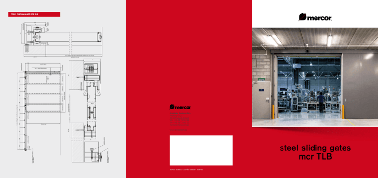
electromagnetic speed regulatorsystem LINNING electromagnetic speed regulatorsystem LINNING hydraulic absorber installation bracket 6.9 hydraulic absorber 128 min 150 786 786 clear opening width of clear passage width of panel 786 total width of panels width of panel roller for LINNING system 786 max 6673 mm – under condition that total surface does not exceed 32.8 m 2 LINNING bracket 786 width of panel 786 320 width of panel opening direction hydraulic absorber 786 roll of counterweight cover of sliding rail counterweight inserted handle height = 1055 786 height of panel length of sliding rail = 2x width of clear opening + 385 min 230 clear passage height 786 min 90 50 sliding rail 213 LINNING bracket installation bracket roll for LINNING 229 786 STEEL SLIDING GATE MCR TLB Arkońska Business Park Arkońska 6/A2 80-387 Gdańsk, Poland tel.: +48 58 732 63 00 fax: +48 58 732 63 02 mercor@mercor.com.pl www.mercor.com.pl steel sliding gates mcr TLB photos: Mateusz Grzanka, Mercor’s archives max 6933 mm - under condition that total surface of gate does not exceed 32.8 m 2 185 MERCOR GROUP DESCRIPTION Mercor is the largest manufacturer and supplier of a comprehensive range of passive fire protection systems in the region of Central and Eastern Europe with a well-developed sales network in the countries of the region. We have achieved a leading position on the Polish, Czech and Slovak market and successfully we are developing in new markets. Mercor Group offers the following range of products: c ustomised fire doors and partitions (hinged doors and gates, sliding doors, glazed doors and fixed partitions, elastic curtains) and doors without fire resistance, natural smoke and heat exhaust systems and roof skylights, fire ventilation systems, fireproofing materials for steel and concrete building structures. STEEL SLIDING GATE MCR TLB EI 60 / EI 120 OPERATING Application: Steel sliding gates mcr TLB are used as the closure of openings in buildings where fire resistance is required. They are specifically designed for industrial buildings, logistic centers, offices, supermarkets etc. Mode of operation: at release of the electric magnet the gate’s leaf is pulled to closed position by the moving load of the counterweight. The counterweight is covered by rectangular steel casing. Fire resistance: 60 minutes (EI 60) and 120 minutes (EI 120) according to EN 1634-1:2009. To assure proper position of the sliding leaf in its axis, a small roller is installed in floor leaf (outside clear opening) and going inside under the sliding. Number of leaves: 1 or 2 (option: telescopic leaves positioning) For transport and installation the leaves and other elements of gate construction are covered with plastic film in order to protect them against mechanical damages. Thickness of the leaf: 90 mm Standard finish: RAL 7035 colour Possible finishes: coated steel (RAL colours: 5010, 9002, 9006, 9007, 9010, 9016) and powder painted steel (any colour from the RAL palette). APPROVALS Tested for fire resistance to EN 1634-1. Classified EI2 60 and EI2 120 to EN 13501-2. DOOR OPENING DIRECTIONS a) sliding gate opening to the left b) sliding gate opening to the right CONSTRUCTION OF GATE The leaf (leaves) of the gate consists of one or more segments of standard width 530 x 1100 mm. Each segment is made of two 0.8 mm galvanized steel sheets glued in with rock wool and gypsum core filling. The edges of the segments are reinforced with steel U-shaped profiles. Total thickness of the gate leaf is 92 mm. The leaf of the gate is hang on the sliding rail. The sliding mechanism consists of: the upper rail, counterweight and driving rolling sets. The upper rail is made of 2-4 mm unpainted, galvanized steel profile fixed to the wall with expansive anchors. The leaf of the gate is connected to its counterweight with a steel cord. DIMENSIONS MINIMUM MAXIMUM WIDTH 1500 mm 16000 mm HEIGHT 1900 mm 4500 mm Larger sizes by individual assessment.

