INSTRUCTIONS 6” Frame-in Kit Housing with Emergency Ballasts
advertisement

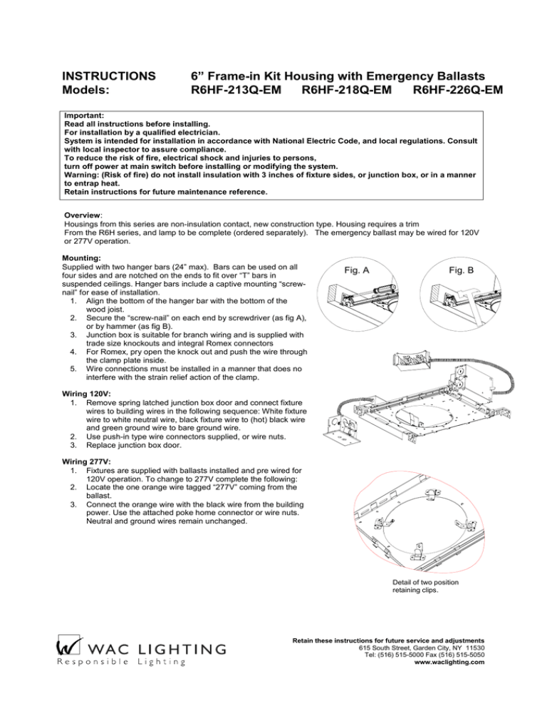
INSTRUCTIONS Models: 6” Frame-in Kit Housing with Emergency Ballasts R6HF-213Q-EM R6HF-218Q-EM R6HF-226Q-EM Important: Read all instructions before installing. For installation by a qualified electrician. System is intended for installation in accordance with National Electric Code, and local regulations. Consult with local inspector to assure compliance. To reduce the risk of fire, electrical shock and injuries to persons, turn off power at main switch before installing or modifying the system. Warning: (Risk of fire) do not install insulation with 3 inches of fixture sides, or junction box, or in a manner to entrap heat. Retain instructions for future maintenance reference. Overview: Housings from this series are non-insulation contact, new construction type. Housing requires a trim From the R6H series, and lamp to be complete (ordered separately). The emergency ballast may be wired for 120V or 277V operation. Mounting: Supplied with two hanger bars (24” max). Bars can be used on all four sides and are notched on the ends to fit over “T” bars in suspended ceilings. Hanger bars include a captive mounting “screwnail” for ease of installation. 1. Align the bottom of the hanger bar with the bottom of the wood joist. 2. Secure the “screw-nail” on each end by screwdriver (as fig A), or by hammer (as fig B). 3. Junction box is suitable for branch wiring and is supplied with trade size knockouts and integral Romex connectors 4. For Romex, pry open the knock out and push the wire through the clamp plate inside. 5. Wire connections must be installed in a manner that does no interfere with the strain relief action of the clamp. Fig. A Fig. B Wiring 120V: 1. Remove spring latched junction box door and connect fixture wires to building wires in the following sequence: White fixture wire to white neutral wire, black fixture wire to (hot) black wire and green ground wire to bare ground wire. 2. Use push-in type wire connectors supplied, or wire nuts. 3. Replace junction box door. Wiring 277V: 1. Fixtures are supplied with ballasts installed and pre wired for 120V operation. To change to 277V complete the following: 2. Locate the one orange wire tagged “277V” coming from the ballast. 3. Connect the orange wire with the black wire from the building power. Use the attached poke home connector or wire nuts. Neutral and ground wires remain unchanged. Detail of two position retaining clips. Retain these instructions for future service and adjustments 615 South Street, Garden City, NY 11530 Tel: (516) 515-5000 Fax (516) 515-5050 www.waclighting.com Emergency Ballast: Fixtures are supplied pre wired to the ballast. Caution: Battery activation contacts have been connected at the factory. The manufacturers’ schematics are provided for reference (one lamp, rapid start ballast). Finishing: Cut out a 6 7/8” hole in the sheetrock. 1. Housing retaining clips have two positions to accommodate various diameters of trim reflectors: Push outward for hole cutting then set clip position appropriate for the trim. 2. Pull socket cup through hole of the trim reflector. 3. Push the trim up to the finished position. 4. Trims have openings opposite the socket to allow adequate clearance for compact fluorescent lamp insertion and removal. Retain these instructions for future service and adjustments 615 South Street, Garden City, NY 11530 Tel: (516) 515-5000 Fax (516) 515-5050 www.waclighting.com


