Installation Instructions - IR-TEC
advertisement

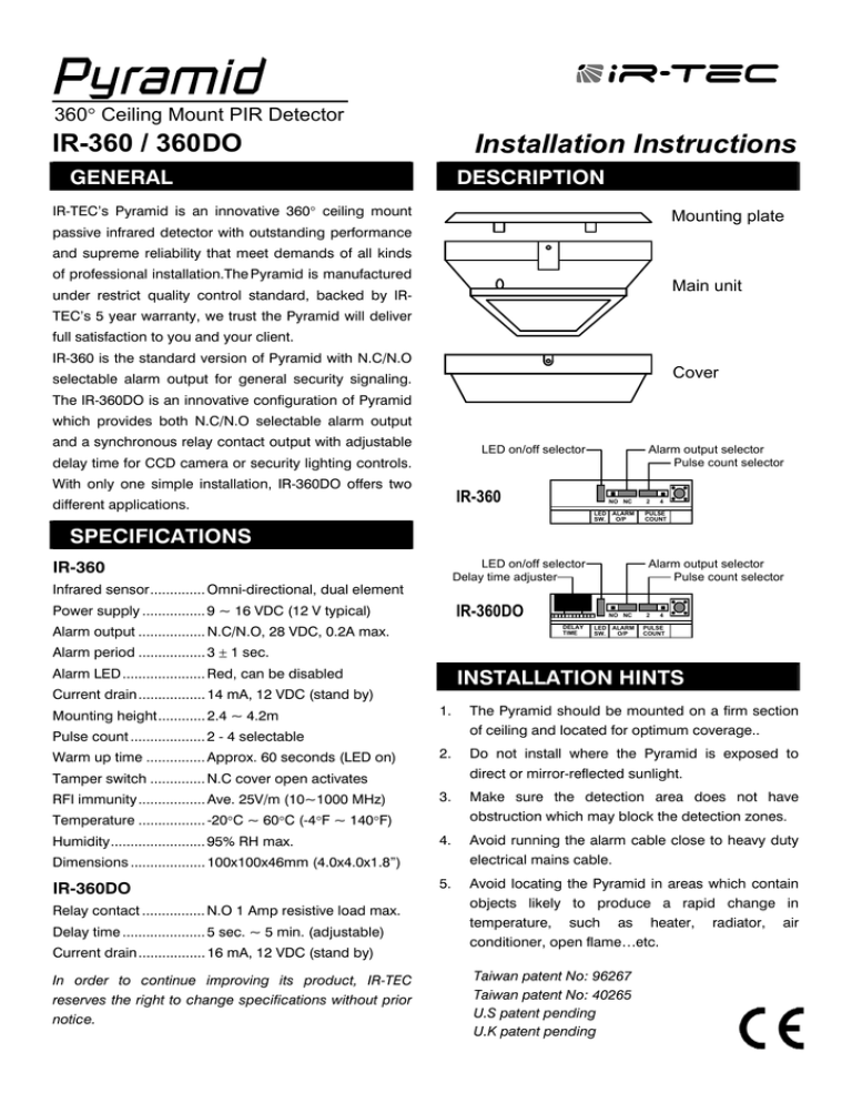
360 Ceiling Mount PIR Detector IR-360 / 360DO Installation Instructions GENERAL DESCRIPTION IR-TEC’s Pyramid is an innovative 360 ceiling mount Mounting plate passive infrared detector with outstanding performance and supreme reliability that meet demands of all kinds of professional installation.The Pyramid is manufactured Main unit under restrict quality control standard, backed by IRTEC’s 5 year warranty, we trust the Pyramid will deliver full satisfaction to you and your client. IR-360 is the standard version of Pyramid with N.C/N.O Cover selectable alarm output for general security signaling. The IR-360DO is an innovative configuration of Pyramid which provides both N.C/N.O selectable alarm output and a synchronous relay contact output with adjustable LED on/off selector delay time for CCD camera or security lighting controls. With only one simple installation, IR-360DO offers two IR-360 different applications. Alarm output selector Pulse count selector NO NC LED ALARM SW. O/P 2 4 PULSE COUNT SPECIFICATIONS IR-360 LED on/off selector Delay time adjuster Infrared sensor.............. Omni-directional, dual element IR-360DO Power supply ................ 9 ~ 16 VDC (12 V typical) Alarm output ................. N.C/N.O, 28 VDC, 0.2A max. Alarm output selector Pulse count selector NO NC DELAY TIME LED ALARM SW. O/P 2 4 PULSE COUNT Alarm period ................. 3 1 sec. Alarm LED ..................... Red, can be disabled INSTALLATION HINTS Current drain................. 14 mA, 12 VDC (stand by) Mounting height............ 2.4 ~ 4.2m 1. The Pyramid should be mounted on a firm section of ceiling and located for optimum coverage.. 2. Do not install where the Pyramid is exposed to direct or mirror-reflected sunlight. 3. Make sure the detection area does not have obstruction which may block the detection zones. 4. Avoid running the alarm cable close to heavy duty electrical mains cable. 5. Avoid locating the Pyramid in areas which contain objects likely to produce a rapid change in temperature, such as heater, radiator, air conditioner, open flame…etc. Pulse count ................... 2 - 4 selectable Warm up time ............... Approx. 60 seconds (LED on) Tamper switch .............. N.C cover open activates RFI immunity ................. Ave. 25V/m (10~1000 MHz) Temperature ................. -20C ~ 60C (-4F ~ 140F) Humidity........................ 95% RH max. Dimensions ................... 100x100x46mm (4.0x4.0x1.8”) IR-360DO Relay contact ................ N.O 1 Amp resistive load max. Delay time ..................... 5 sec. ~ 5 min. (adjustable) Current drain................. 16 mA, 12 VDC (stand by) In order to continue improving its product, IR-TEC reserves the right to change specifications without prior notice. Taiwan patent No: 96267 Taiwan patent No: 40265 U.S patent pending U.K patent pending INSTALLATION & WIRING 1. Loosen the cover locking screw, separate the cover and main unit. Release the fixing screws (2) to disassemble the main unit and mounting plate. 2. Fixing the mounting plate with screws (2) at selected location on the ceiling. 3. Strip the outer sleeve of alarm cable. (6-core for IR360, 8-core for IR-360DO). Run the coded wires through the cable access and connect to the corresponding terminal blocks according to the following instructions. 4. Replace the cover and fasten the locking screws. Apply DC power supply, then walk test can be proceeded. Cable access Terminal blocks ALARM TAMPER IR-360 WALK TEST Once the detector has been set up, walk test the entire area where coverage is desire. Should the coverage be incomplete, re-adjust or relocate the detector to obtain full coverage. Once coverage is as required, the alarm LED may be disabled by pull off LED jumper head. Regular walk testing must be carried out, as part of your maintenance visits or at least once a year.) DELAY TIME The synchronous relay contact of IR-360DO can be applied to control CCD camera, security lighting or other security equipment which are required to be activated when intrusion is detected. Delay time can be adjusted from approximate 5 seconds to minutes by rotating the thumb wheel of the delay time adjuster in clockwise direction. DETECTION PATTERN Cable access Terminal blocks RELAY ALARM Model: IR-360 / IR-360DO Side View TAMPER IR-360DO TAMPER : 24 hours N.C loop of control panel : 9 ~ 16 VDC power supply ALARM : Zone loop of control panel (N.C / N.O) RELAY : Max. 2 Amp resistive load (Only IR-360DO) 8 6 (26.5) (20) 4 2 (12.5) (6.5) 0 (0) 2.7 (9) 3.0 (10) 3.6 (12) 4.2 (14) m m (ft.) 4 6 2 (6.5) (12.5) (20) (ft.) Top View PULSE COUNT The Pyramid features intelligent pulse count which can effectively prevent false alarms cause by environmental interference. The IPC of Pyramid can be set to count 2 or 4 pulses by placing the jumper head on the corresponding pins. Alarm signal will only be sent if the selected pulses are generated within delay period (about 20 seconds). The state-of-the-art IPC circuitry analyzes the difference of pulse width, so when a true motion is detected, the subsequent pulse signal will tide over the pulse setting and report an alarm immediately. The conventional pulse count detector could possibly miss an intrusion due to an inevitable time delay for verifying the number of pulse. 2001/12/11 058-36000-000 V1.0 Max. Detection Range (at 25C) 2.7 3.0 3.3 Mounting m (9) (10) (11) Height (ft.) 6x6 8x8 10 x 10 Detection (20 x 20) (26 x 26) (33 x 33) Range 3.6 (12) 11 x 11 (36 x 36)

