Impact of Setup and Pulse Generator on Automotive
advertisement

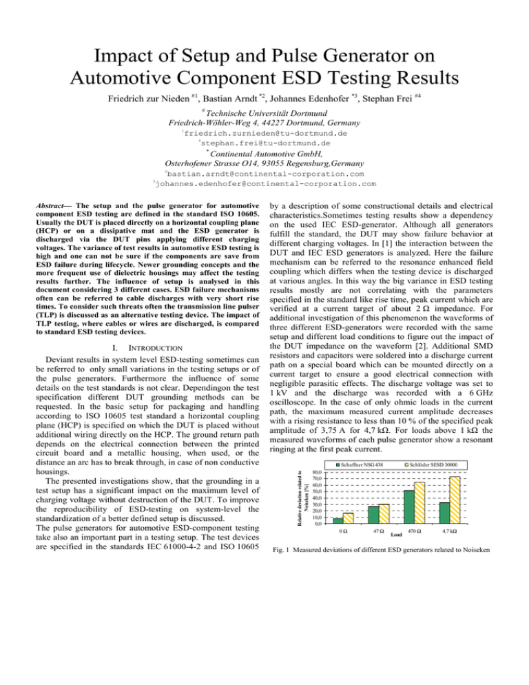
Impact of Setup and Pulse Generator on Automotive Component ESD Testing Results Friedrich zur Nieden #1, Bastian Arndt *2, Johannes Edenhofer *3, Stephan Frei #4 # Technische Universität Dortmund Friedrich-Wöhler-Weg 4, 44227 Dortmund, Germany 1 friedrich.zurnieden@tu-dortmund.de 4 stephan.frei@tu-dortmund.de * Continental Automotive GmbH, Osterhofener Strasse O14, 93055 Regensburg,Germany 2 bastian.arndt@continental-corporation.com johannes.edenhofer@continental-corporation.com Abstract— The setup and the pulse generator for automotive component ESD testing are defined in the standard ISO 10605. Usually the DUT is placed directly on a horizontal coupling plane (HCP) or on a dissipative mat and the ESD generator is discharged via the DUT pins applying different charging voltages. The variance of test results in automotive ESD testing is high and one can not be sure if the components are save from ESD failure during lifecycle. Newer grounding concepts and the more frequent use of dielectric housings may affect the testing results further. The influence of setup is analysed in this document considering 3 different cases. ESD failure mechanisms often can be referred to cable discharges with very short rise times. To consider such threats often the transmission line pulser (TLP) is discussed as an alternative testing device. The impact of TLP testing, where cables or wires are discharged, is compared to standard ESD testing devices. I. INTRODUCTION Deviant results in system level ESD-testing sometimes can be referred to only small variations in the testing setups or of the pulse generators. Furthermore the influence of some details on the test standards is not clear. Dependingon the test specification different DUT grounding methods can be requested. In the basic setup for packaging and handling according to ISO 10605 test standard a horizontal coupling plane (HCP) is specified on which the DUT is placed without additional wiring directly on the HCP. The ground return path depends on the electrical connection between the printed circuit board and a metallic housing, when used, or the distance an arc has to break through, in case of non conductive housings. The presented investigations show, that the grounding in a test setup has a significant impact on the maximum level of charging voltage without destruction of the DUT. To improve the reproducibility of ESD-testing on system-level the standardization of a better defined setup is discussed. The pulse generators for automotive ESD-component testing take also an important part in a testing setup. The test devices are specified in the standards IEC 61000-4-2 and ISO 10605 by a description of some constructional details and electrical characteristics.Sometimes testing results show a dependency on the used IEC ESD-generator. Although all generators fulfill the standard, the DUT may show failure behavior at different charging voltages. In [1] the interaction between the DUT and IEC ESD generators is analyzed. Here the failure mechanism can be referred to the resonance enhanced field coupling which differs when the testing device is discharged at various angles. In this way the big variance in ESD testing results mostly are not correlating with the parameters specified in the standard like rise time, peak current which are verified at a current target of about 2 Ω impedance. For additional investigation of this phenomenon the waveforms of three different ESD-generators were recorded with the same setup and different load conditions to figure out the impact of the DUT impedance on the waveform [2]. Additional SMD resistors and capacitors were soldered into a discharge current path on a special board which can be mounted directly on a current target to ensure a good electrical connection with negligible parasitic effects. The discharge voltage was set to 1 kV and the discharge was recorded with a 6 GHz oscilloscope. In the case of only ohmic loads in the current path, the maximum measured current amplitude decreases with a rising resistance to less than 10 % of the specified peak amplitude of 3,75 A for 4,7 kΩ. For loads above 1 kΩ the measured waveforms of each pulse generator show a resonant ringing at the first peak current. Schaffner NSG 438 Relative deviation related to Noiseken [%] 3 Schlöder SESD 30000 80,0 70,0 60,0 50,0 40,0 30,0 20,0 10,0 0,0 0Ω 47 Ω Load 470 Ω 4,7 kΩ Fig. 1 Measured deviations of different ESD generators related to Noiseken DUT 2 DUT 3 DUT 4 DUT 5 Fig. 2 Testing configuration: DUT housing connected to HCP 16 14 12 10 8 6 4 2 0 DUT 12 DUT 13 DUT 14 DUT 15 Fig. 3 Testing configuration: DUT housing isolated, GND-pin connected to HCP In Fig. 1 the deviation of the maximum peak amplitudes of a Schaffner NSG 438 and Schlöder SESD 30000 IEC ESD generator are compared related to a Noiseken TC-815 generator. For high resistances in the current path a deviation of more than 70 % was measured with respect to the lowest amplitude. II. In this chapter with respect to automotive ESD figured out. DUT 11 ANALYSIS OF TESTING SETUPS the impact of different grounding concepts the testing setup are investigated. For testing 3 typical configurations can be A. Comparison of grounding concepts 1) Grounding Concepts • DUT housing connected to HCP Fig. 2 shows the basic setup where the DUT is placed directly on the coupling plane. The PCB is connected in this case to the housing. Often additional capacitors are soldered between PCB ground and housing screws for EMC filtering. • DUT-GND-PIN connected to HCP In Fig. 3 the ground pin of the DUT is connected to the coupling plane. The housing is isolated against the ground plane. High ESD current pulses can be lead to ground via parallel ESD-protection elements. • DUT isolated According to Fig. 4 there is no direct path to the coupling plane. The reference potential of the DUT is not defined during the ESD-test. Mainly the board to HCP capacitance defines the current path to ground. The impact of the grounding concept during ESD tests is explained by a testing series and analysed by measurement using a realistic setup. 2) Detecting the failure level of automotive ECUs A testing series was performed with an automotive airbagECU. Five units were each tested at the same time in the same setup with an ESD robot system to assure a high reproducibility. During the test the charging voltage of the IEC generator was increased in steps of 1 kV until failure ESD failure voltage [kV] DUT 1 ESD failure voltage [kV] ESD failure voltage [kV] 16 14 12 10 8 6 4 2 0 16 14 12 10 8 6 4 2 0 DUT 6 DUT 7 DUT 8 DUT 9 DUT 10 Fig. 4 Testing configuration: DUT housing isolated, no connection to HCP behaviour of the devices could be detected. The testing results show a dependency on the applied grounding condition (Fig. 2, Fig. 3 and Fig. 4). The lowest charging voltage that causes a failure is 7 kV in the configuration where the DUT is placed on the ground plane. With a connected ground pin the charging voltage level leading to failure increases to 9 kV. Another level of 12 kV can be reached if the DUT is isolated. Note that in this case the applied charging voltages are spread over 4 kV and the test reproducibility is low. 3) Current measurements To analyse the impact of the test setup, the current shapes of different pulse generators were recorded for each of the described grounding concept. The measurements were performed using a modified automotive ECU with a metal housing where a part of the original PCB near the connector was removed and replaced by small rectangular testing board of 3 cm and 5 cm edge length, in order to place defined termination impedances and a current probe. The integrated testing board which is shown in Fig. 5 contains a 50 Ω PCB trace surrounded by a layer which is connected to the ground layer of the ECU PCB. One ECU pin was connected to the PCB trace so that the pulse generator can be discharged directly via a pin of the ECU connector outside the housing. A 10 Ω, 100 Ω or a 1 kΩ SMD resistor was soldered into the current path between the strip line and the ground surface. Thus a realistic measurement setup was created considering the influence of the ECU pin, a PCB trace and finally the grounding. Fig. 5 Measurement setup: Integrated testing board with resistive loads and current probe The waveforms were recorded with a 6 GHz oscilloscope measuring the injected current with a Tektronix CT 6 probe for 500 V charging voltage of the pulse generator. To isolate the DUT from the coupling plane a layer of 1 cm polystyrene was used. The connection from the ground pin to the HCP was realized by a wire of 10 cm length and 0,5 mm² diameter. The rise time, peak current and the maximum charge were calculated for each grounding concept. Fig. 6 and Fig. 7 show the deviation between the different grounding conditions for one ESD generator for the example of the peak current and peak charge. The values are related to the setup where the DUT is placed directly on the HCP. DUT housing isolated DUT housing isolated, GND pin connected to HCP 120 100 80 60 40 20 0 80 Deviation of charge [%] Deviation of peak current [%] 100 DUT housing isolated, GND pin connected to HCP 60 40 20 0 10 Ω 100 Ω 1000 Ω Load Fig. 6 Measured peak currents of IEC pulse related to the setup with DUT housing connected to HCP By comparing the simulated and measured waveforms the influence of the capacitance between ground plane of PCB and HCP is shown in Fig. 9. In case of the isolated DUT the peak amplitude and the fall time decrease. The charge reaches about 10 % of the non isolated case. A part of the charge is conducted through the ground cable of the ESD generator which could be referred to the ringing in the measured current shape. Measured discharge with non isolated DUT 0.6 10 Ω 100 Ω 1000 Ω Load Fig. 7 Measured charge of IEC pulse related to the setup with DUT housing connected to HCP The measured peak currents with an isolated DUT reach about 60 % in comparison to a non isolated device. Is the ground pin connected nearly 90 % is reachable. With respect to the charge the difference between the concepts becomes more significant. Only 10 % of the transmitted charge regarding an isolated DUT was measured. A connection between the ground pin and HCP ensures that the full charge is transmitted to the DUT. Nevertheless the measured charge decreases with an increasing impedance. The rise times of the pulses increase about 300 ps in comparison to the measured values at a 2 Ω current target for pulse verification. No difference was observed between a connected ground pin and a non-isolated DUT. Therefore the effect can be referred to the ECU pin and the PCB trace representing an additional inductivity in the current path. With higher loads the ringing increases and leads to decreasing rise times. 4) Simulation The impact of an isolated DUT without any connection to the coupling plane was analysed by simulation for an 1 kΩ load. Fig. 8 shows the simulation setup for the test case with an isolated DUT. The isolation is modelled by an additional capacitor in the ground path. The charging voltage of a simple ESD generator model was set to 500 V [3]. The pulse first propagates through the DUT pin which is considered with an inductor of 3 nH. For the PCB trace on the testing board a 50 Ω lossless transmission line model with 5 cm length is applied. Current [A] DUT housing isolated Fig. 8 Simulation setup for the estimation of the PCB to HCB capacitance in case of an isolated DUT Measured discharge with isolated DUT 0.5 Simulated discharge with isolated DUT 0.4 Simulated discharge with non isolated DUT 0.3 0.2 0.1 0 0 10 20 30 40 50 60 70 80 Time [ns] Fig. 9 Comparison of measured and simulated waveforms with isolated and non-isolated DUT with 1 kΩ load III. COMPARABILITY OF IEC ESD-GENERATOR AND TLP In most cases the main part of a TLP forms a 50 Ω coaxial cable which is charged and discharged via a switching relay like in an IEC generator. This form is mainly used by semiconductor manufacturers where a DUT can be soldered on a testing PCB and the shield of the coaxial cable can be connected directly to the PCB ground plane. A sharp pulse with very short rise times can be conducted with low losses. Due to ESD failure of automotive systems caused by discharges of wiring harness, the TLP also is discussed as an alternative testing device [4]. In this way ESD testing could be also performed with very sharp pulses and lower rise times than the IEC generator. An additional testing series was performed with the same setup presented in section II. Two ESD generators are compared with a 50 Ω coaxial cable and a single wire discharge as shown in Fig. 5. First the conductors were discharged directly via the DUT pin. The impedance of the wire was set to about 250 Ω by separating it from the coupling plane by 3 cm polystyrene. The voltage of the HV-source was set to 500 V. Fig. 10 and Fig. 11 show the results of the measured peak currents and rise times in relation to a Noiseken IEC generator for 100 Ω load. Due to the low impedance the measured peak current of the coaxial cable discharge exceeds 300 %. The Peak current ratio related to Noiseken Schlöder SESD30000 Charged coaxial cable Charged wire 4,0 Wire ending Spark gap Spark gap 2 Rise time [ns] 7 6 5 4 3 2 1 0 1,5 1 0,5 0 500 1000 Load [Ω] 500 2000 1000 2000 Load [Ω] 3,0 Fig. 13 Deviation of measured peak currents for a dataset of 20 discharges with 100 Ω load 2,0 1,0 0,0 DUT housing on HCP DUT isolated without HCP connection DUT isolated with HCP connection Fig. 10 Measured peak currents of different testing devices related to the Noisken ESD generator for 100 Ω load Rise time ratio related to Noiseken Wire ending Peak current [A] ratio gets more stable for testing devices with higher impedances, but the charged single wire still reaches nearly 200 % of the Noiseken generator. Typical measured rise times for the charged wire are about 200 ps. Thus the ratio in comparison to an IEC generator is significantly low. Rise times of coaxial cable discharges can be compared to an IEC ESD generator for typical automotive ESD testing setups. 1,2 1,0 0,8 0,6 0,4 0,2 0,0 Schlöder SESD 30000 Charged coaxial cable DUT housing on HCP Charged wire DUT isolated without HCP conne cti on DUT isolated with HCP connection Fig. 11 Measured rise times of different testing devices related to the Noisken ESD generator for 100 Ω load IV. NEW PROPOSAL FOR PACKAGING AND HANDLING TESTING Basic investigations have shown that the current shape of pulses from a coaxial cable is mostly depending on the quality of the ground connection which affects directly the pulse shape. An alternative setup which avoids a dependency on the grounding path could be the discharge of a single wire like it is shown in Fig. 12. Fig. 14 Deviation of measured rise times for a dataset of 20 discharges 100 Ω load V. CONCLUSION The results of the testing series of section II can be explained well by the outcome of the analysis performed on a modified ECU. The measured flown charge in case of an isolated DUT reaches only about 10 % of the non–isolated case. In the presented investigations the influence of the isolation can be modelled by an additional 15 pF capacitor in the ground path. A significant impact of an isolated DUT with a connected ground pin concerning the charge, rise time or peak current was not observed compared to a non-isolated DUT. Today some TLP systems exist which even have been adapted to the standardized IEC pulse shape [5]. For automotive purposes it is difficult to connect the coaxial structure of the TLP to a standard ECU connector. One solution could be to connect the shield of the coaxial cable directly to the HCP with a wire. The drawback of this solution is a reduced rise time that is influenced by the additional inductivity in the ground path. A single wire discharge is proposed as an alternative testing method for automotive component ESD testing. A stable waveform is obtained by the use of a spark gap with small spheres. The impedance of the charged wire can be adjusted by changing the distance to the horizontal coupling plane. ACKNOWLEDGMENT This contribution was supported from the German Federal Ministry of Education and Research in the context of the MEDEA+ project SPOT-2 2T205. REFERENCES [1] Fig. 12 Possible setup for single wire discharges with low rise times Here the HCP is used as a current return path and the impedance of the testing device depends on the distance to the coupling plane. Investigations have shown that reproducible pulses can be generated by using a spark gap with spherical electrodes. Fig. 13 and Fig. 14 show the standard deviation of a dataset of 20 discharges via a spark gap and the simple wire ending for the peak current and the rise time. For a charging voltage of 2000 V the standard deviation of the manually performed testing series is about 2 % in case of the rise time. Further reduction of standard deviation is possible by irradiating the gap with ultra violet light. [2] [3] [4] [5] J. Koo, Q. Cai, K. Wang, J. Maas, T. Takahashi, A. Martwick, and D. Pommerenke, “Correlation Between EUT Failure Levels and ESD Generator Parameters,” IEEE transactions on Electromagnetic Compatibility, vol. 50, no. 4, 2008. F. zur Nieden, B. Arndt, J. Edenhofer, and S. Frei, “Vergleich von ESD-System-Level Testmethoden für Packaging und Handling,” ESDFORUM, Berlin, 2009. K. Glöser, “Alternative methoden des Überspannungs- und esdschutzes,” dissertation, Technische Universität Kaiserslautern, Germany, 2005. B. Arndt, F. zur Nieden, R. Pöhmerer, J. Edenhofer, and S. Frei, “Comparing Cable Discharge Events to IEC 61000-4-2 or ISO 10605 Discharges,” Proceedings, 20th Int. Zurich Symposium on EMC, Zurich, 2009. Y. Cao, D. Johnsson, B. Arndt, M. Stecher, and S. Frei, “A TLP-based Human Metal Model ESD-generator for device qualification according to IEC 61000-4-2,” Asia-Pacific Symposium on Electromagnetic Compatibility , Beijing, 2010.


