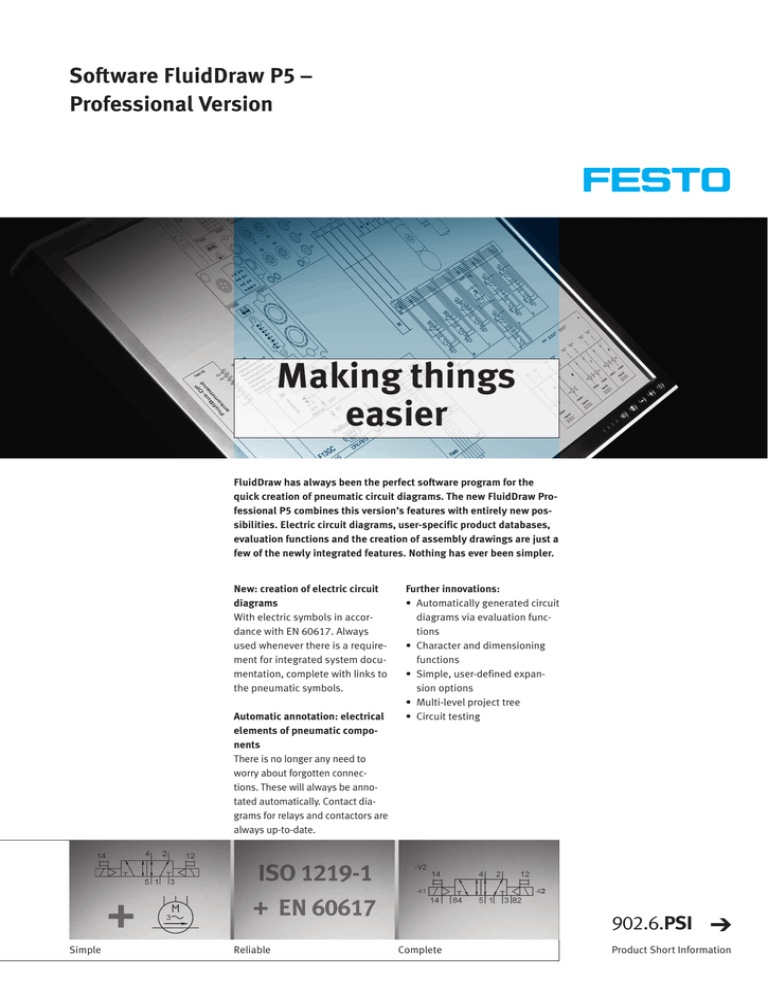
Making things easier
advertisement

Software FluidDraw P5 – Professional Version Making things easier FluidDraw has always been the perfect software program for the quick creation of pneumatic circuit diagrams. The new FluidDraw Professional P5 combines this version’s features with entirely new possibilities. Electric circuit diagrams, user-specific product databases, evaluation functions and the creation of assembly drawings are just a few of the newly integrated features. Nothing has ever been simpler. New: creation of electric circuit diagrams With electric symbols in accordance with EN 60617. Always used whenever there is a requirement for integrated system documentation, complete with links to the pneumatic symbols. Automatic annotation: electrical elements of pneumatic components There is no longer any need to worry about forgotten connections. These will always be annotated automatically. Contact diagrams for relays and contactors are always up-to-date. Further innovations: • Automatically generated circuit diagrams via evaluation functions • Character and dimensioning functions • Simple, user-defined expansion options • Multi-level project tree • Circuit testing 902.6.PSI Simple Reliable Complete Product Short Information Software FluidDraw P5 – Professional Version Pneumatic system with electrical elements annotated • Electrical elements of pneumatic systems are clearly visible • Contact diagrams for relay and contactors are always up-to-date • Intelligent link between symbols and bill of materials (BOM) item Simple expansion options • Easy to integrate: user-defined symbols and libraries • Simple yet effective import/export interfaces for custom product databases • User-specific text translation tables for multilingual purposes Circuit testing Optional testing for error-free circuit generation either during the process or via a menu option: • Dual designation (equipment identifier) • Double cross-reference markers • Missing link destinations • Objects lying on top of one another • Cross-connection cables • Open connections • Objects lying outside of the drawing area • Non-allocated terminals Multi-level project tree Transfer of drawing frames and project data to subordinate project nodes and sheets: avoids the need to post-process each individual sheet! Festo AG & Co. KG Ruiter Strasse 82 73734 Esslingen www.festo.com Tel. +49 711 347 0 Fax +49 711 347 21 44 service_international@festo.com Subject to change Character and dimensioning functions • Integrated drawing functions available for the creation of custom symbols, including all necessary basic symbols such as lines, polygons, rectangles, circles, ovals, text and graphics, as well as classified connection points • Includes intelligent dimensioning feature for the creation of assembly drawings • Floating navigation window provides a better overview 2010/12 Automatic generation: circuit diagrams created via evaluation functions • BOM with arbitrary column order • Sorting function with a variety of options such as total BOM or itemised BOM • Evaluation functions such as terminal diagram, cable diagram and cable list, particularly for electric circuits

