7960-464
advertisement

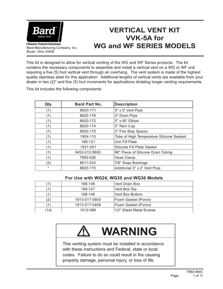
Bard Manufacturing Company, Inc. Bryan, Ohio 43506 VERTICAL VENT KIT VVK-5A for WG and WF SERIES MODELS This kit is designed to allow for vertical venting of the WG and WF Series products. The kit contains the necessary components to assemble and install a vertical vent on a WG or WF unit requiring a five (5) foot vertical vent through an overhang. The vent system is made of the highest quality stainless steel for this application. Additional lengths of vertical vents are available from your dealer in two (2)* and five (5) foot increments for applications dictating longer venting requirements. This kit includes the following components: Qty. B a rd P a rt N o . D escrip tio n (1 ) (1 ) (1 ) (1 ) (1 ) (1 ) (1 ) (1 ) (1 ) (1 ) (3 ) * 8620-171 8620-176 8620-172 8 6 2 0 -1 7 4 8620-175 1904-110 168-121 1921-051 5452-012-9600 7950-026 8611-033 8620-170 3" x 5' Vent P i pe 3" D rai n P i pe 3" x 90° E lbow 3" Rai n C ap 3" F i re Stop Spacer Tube of Hi gh Temperature S i li cone S ealant Uni t F i ll P late S i li cone F i ll P late Gasket 96" P i ece of S i li cone D rai n Tubi ng Hose C lamp 7/8" S nap B ushi ngs A ddi ti onal 3" x 2' Vent P i pe F o r U se w ith WG24, WG30 an d WG36 Mo d els (1 ) (1 ) (1 ) (2 ) (1 ) (1 4 ) 168-146 168-147 168-148 1913-017-0800 1913-017-0408 1012-086 Vent D rai n B ox Vent B ox Top Vent B ox B ottom F oam Gasket (P oron) F oam Gasket (P oron) 1/2" S heet Metal S crews WARNING This venting system must be installed in accordance with these instructions and Federal, state or local codes. Failure to do so could result in fire causing property damage, personal injury, or loss of life. Page 7960-464C 1 of 11 IMPORTANT NOTICE JOINT PROCEDURE 1. The vent system must be free to expand and contract. Pipe must be properly supported. 1. The outside of male end and inside of female end of pipe must be cleaned before applying silicone bead. Remove dirt, grease and moisture from surface to be sealed. Dry surface or allow to dry thoroughly. 2. The firestop must be used as lateral support as shown and at least one support collar at the base of the vertical run. 3. Examine all components for possible shipping damage prior to installation. 4. Check for unrestricted vent movement through ceiling and roof penetration. 5. Use only the supplied joint sealant. Do not use other brands. 2. Apply high temperature silicone approximately one half inch from end around male end of pipe and along both sides of seam for one inch in an even 1/4" bead as per Figure 1. 3. Pipes can now be pushed together as far as they will go. 4. Tighten gear clamps (15 In./Lb. max.). 5. Check for unrestricted vent movement through ceiling and roof penetrations. 6. Allow the sealant to cure for one hour before operating the appliance. Length of time required for full cure depends upon thickness of application and other factors such as weather, ambient temperature, humidity, etc. All sealants must be used within the time limitations marked. FIGURE 1 APPLYING SILICONE TO PIPES 7960-464C Page 2 of 11 TABLE 1 CLEARANCE TO COMBUSTIBLES System Operating Temperature 480°F ( 249°C) Clearnace Enclosed Horiz ontal Vertical 8" (200 mm) 4" (100 mm) VERTICAL VENTING Note: The vent termination must be at least 3 feet (1 M) above the roof line and 2 feet (.61 m) higher than any part of a structure within 10 feet (3.1 m). The total vertical distance of the vent system from appliance flue collar to the rain cap termination shall not exceed 20 feet. The clearance to combustibles inside a chase shall be no less than 4" (100 mm). 1. Prior to beginning the installation, loosely assemble all parts required to make sure all parts are present. 2. Locate position for venting system and proceed to cut holes for firestop support and firestop spacer. All vertical installations require the use of a support. 3. Refer to JOINT PROCEDURE (Figure 1) before assembling system. 4. Install system joining pipe as required up through roof (Figure 2 for WG24, WG30 & WG36; Figure 2A for WG42, WG48, WG60; Figure 2B for all WF models). NOTE: A firestop must be provided when a vent passes through a combustible floor or ceiling. The opening must be framed as for the support since the support also serves as a firestop. 5. The roof flashing can now be installed. Where the vent passes through the roof a flashing must be used to maintain the required clearances and to protect from the elements. The framed opening must be large enough to provide the necessary clearances to combustibles, taking into account the slope of the roof. The flashing can be used on slopes from flat to 6/12 pitch. Install the flashing while holding the pipe centered in the opening. Fasten the flashing to the roof under the roofing material upslope from the pipe and above the roofing material below the pipe. Seal as required using high temperature silicone. 6. Attach rain cap using the locking band as for regular pipe joints. Clearance Unenclosed Horiz ontal Vertical Sealant Required 1" (25 mm) N/A G.E. 106 Z-Flex Z-Vent Sealant 7. FOR VENTING MODELS WG24, WG30 & WG36 REFER TO FIGURE 3. For these models a vent box is required to be installed on the front of the unit. The drain tee is then supported by this box. The drain line is also enclosed inside the box to protect it from the weather. To install this system first TURN OFF ALL POWER TO UNIT. Install drain tee onto the draft inducer transition after applying the high temperature silicone sealant to ensure an airtight seal between the tee and transition. Using two (2) self-drilling screws (provided), secure the tee with the drain stub in the straight down or "six o'clock" position. Knockout the 7/8" slug located in the front panel just beneath the drain tee. Install one of the 7/8" snap bushings in this hole. Route the silicone drain tube through the unit as shown in Figure 5. For WG24, WG30 and WG36 models, the drain tube will then be run through the snap bushing just below the drain tee and connected to the drain tee stub. Assemble vent box and install box seals as shown in Figure 3A. Install vent box to the unit as shown in Figure 3. There are a total of six (6) holes that secure the vent box to the unit. Three (3) of these holes are already punched and three (3) will need to be drilled using an 1/8 inch drill bit. FOR VENTING MODELS WF050, WF075, WF100 & WF125 REFER TO FIGURE 4. The drain tee must be installed onto the draft inducer transition. In order to do this the existing 3" stainless "straight through" connector must first be removed. TURN OFF ALL POWER TO UNIT. Unplug the inducer at the mating two pin connector and remove inducer by removing five (5) screws. Remove the "straight through" connector and replace with the drain tee. The drain tube must be in the down position. Use the high temperature silicone sealant provided with this kit to ensure an airtight seal between the inducer outlet and the drain tee. Reinstall the two screws in the drain tee and secure the inducer and inducer gasket to the collector box with five (5) screws. Plug in inducer. Page 7960-464C 3 of 11 FIGURE 2 VERTICAL VENTING INSTALLATION FOR WG24, WG30 & WG36 MODELS 7960-464C Page 4 of 11 FIGURE 2A VERTICAL VENTING INSTALLATION FOR WG42, WG48 & WG60 MODELS Page 7960-464C 5 of 11 FIGURE 2B VERTICAL VENTING INSTALLATION FOR ALL WF MODELS 7960-464C Page 6 of 11 FIGURE 3 INSTALLATION OF DRAIN BOX MODELS WG24, WG30 & WG36 REMOVE EXISTING SCREW AND USE HOLE FOR BOX STANDARD SCREWS INSERTED INTO EXISTING HOLES RIGHT FRONT CORNER OF UNIT EXISTING HOLES BOX TOP WITH PORON GASKET ON BACK TOP BEND TRANSITION ON IDB BLOWER APPLY HIGH TEMP. SILICONE SEALANT EVENLY AROUND TRANSITION DRAIN TEE REMOVE 7/8" KNOCKOUT DRAIN STUB INSERT BUSHING SELF DRILLING SCREWS DRAIN TUBE ATTACHES TO DRAIN STUB AND RUNS THROUGH BUSHING STANDARD SCREW INSERTED INTO UNIT HOLE BOX WITH PORON GASKET ON BACK SIDE BENDS SELF DRILLING SCREWS USED TO ATTACH TEE TO TRANSITION MIS-1687 Page 7960-464C 7 of 11 FIGURE 3A VENT BOX -- ASSEMBLY AND SEALS MODELS WG24, WG30 & WG36 APPLY 4 3/8" PIECE OF PORON GASKET ON BOX TOP TRIM (6) CHAMFERED CORNERS (OPTIONAL) APPLY 8" PIECES OF PORON GASKET TO FLANGES OF DRAIN BOX BOX TOP DRAIN BOX ATTACH BOTTOM OF BOX WITH (3) SCREWS BOX BOTTOM MIS-1686 7960-464C Page 8 of 11 FIGURE 4 INSTALLATION OF DRAIN TEE MODELS WF050, WF075, WF100 & WF125 INDUCER GASKET INDUCER SEALANT STRAIGHT THRU CONNECTOR DRAIN TEE (PART #8620-176) DRAIN FITTING DOWN MIS-2334 Page 7960-464C 9 of 11 INSTALLING DRAIN TUBING To install the silicone drain tubing, refer to Figure 5 and remove the two knockouts shown. Install the two snap bushings (included) into the 7/8" holes. Attach one end of the drain tubing to the drain tee fitting and secure with the hose clamp included. Route the drain tubing as shown in Figure 5 as to form a "trap" in the line. Make sure that the tubing is run through all four holes so it exits the lower unit base. NOTE: Do not use any other type of material for the purpose of draining this vent system. Doing so could result in damage to the unit. Once the drain tubing is installed, install the "Silicone Fill Plate Gasket" and "Unit Fill Plate" as shown in Figure 6. Follow installation procedure exactly – as this is a critical water seal. (Used for WG42, WG48, WG60 & all WF models only.) FIGURE 5 INSTALLING DRAIN TUBING ATTACH DRAIN TUBE TO TRANSITION WRAP DRAIN TUBE AROUND MANIFOLD SUPPORT BRACKET LEAVING THE TUBING LOOSE ENOUGH TO AVOID KINKING REMOVE KNOCKOUT, INSTALL SNAP BUSHINGS, AND ROUTE TUBE ROUTE TUBE THROUGH HOLE IN BASE MIS-2335 7960-464C Page 10 of 11 FIGURE 6 FILL PLATE INSTALLATION MODELS WG42, WG48, WG60 AND ALL WF MODELS WF MODEL SHOWN Page 7960-464C 11 of 11


