An On-board Algorithm for Automatic Sun
advertisement

An On-board Algorithm for Automatic Sun-pointing of a Spinning Satellite
S. Grahn
Science Systems Division, Swedish Space Corporation, Sweden
_____________________________________
Abstract
Autonomous control of the orientation of the
rotation axis of a spin-stabilised satellite is a
desirable feature for small projects in order to
reduce the need for support from the ground. Spin
stabilisation is mostly used in space plasma physics
satellites, both to keep wire booms taut but also
make particle sensors scan in various directions.
Two different orientations of the spin axis are
common; perpendicular to the orbital plane
(cartwheel) or Sun-pointing.
Simple on-board control algorithms using magnetic
actuators can be used for both orientations. For the
cartwheel orientation (spin axis aligned to the orbit
normal) the classical "minus-B-dot" law can be
used in high inclination orbits to automatically
control the satellites' spin axis. In this algorithm the
projection of the Earth’s magnetic field along the
spin axis is measured. The sign of the time
derivative of this measurement is used to determine
the polarity of the magnetic dipole moment of a
magnetic torque coil with its dipole moment
aligned with the spin axis. By applying this control
law the spin axis aligns with the orbit normal1.
A simple control law algorithm for automatically
pointing the spin axis in the direction of the sun
using a sun-sensor, a magnetometer and magnetic
actuators is also possible. A Swedish patent
application (no. 9702333-7) for this algorithm has
been submitted. The principles of this control law
are described in this technical note.
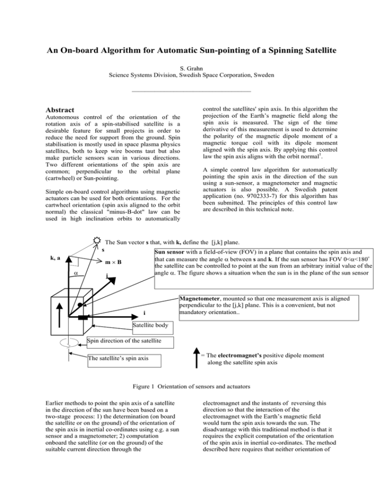
5 The Sun vector s that, with k, define the [j,k] plane.
s
k, a
Sun sensor with a field-of-view (FOV) in a plane that contains the spin axis and
o
that can measure the angle α between s and k. If the sun sensor has FOV 0<α<180
the satellite can be controlled to point at the sun from an arbitrary initial value of the
angle α. The figure shows a situation when the sun is in the plane of the sun sensor
m×B
α
j
i
Magnetometer, mounted so that one measurement axis is aligned
perpendicular to the [j,k] plane. This is a convenient, but not
mandatory orientation..
Satellite body
Spin direction of the satellite
The satellite’s spin axis
= The electromagnet’s positive dipole moment
along the satellite spin axis
Figure 1 Orientation of sensors and actuators
Earlier methods to point the spin axis of a satellite
in the direction of the sun have been based on a
two-stage process: 1) the determination (on board
the satellite or on the ground) of the orientation of
the spin axis in inertial co-ordinates using e.g. a sun
sensor and a magnetometer; 2) computation
onboard the satellite (or on the ground) of the
suitable current direction through the
electromagnet and the instants of reversing this
direction so that the interaction of the
electromagnet with the Earth’s magnetic field
would turn the spin axis towards the sun. The
disadvantage with this traditional method is that it
requires the explicit computation of the orientation
of the spin axis in inertial co-ordinates. The method
described here requires that neither orientation of
the spin axis nor the sun in inertial co-ordinates
need to be determined or known. The present
method uses a sun sensor, a magnetometer and an
electromagnet, the magnetic dipole moment of
which is parallel or anti-parallel to the spin axis and
can change sign when the current through the
electromagnet is reversed. The angle between the
spin axis and the direction of the sun need to be
measured onboard the satellite. The direction of the
current through the electromagnet shall be such that
the magnetic dipole moment of the electromagnet
along the spin axis has the same sign as the
component of the earth’s magnetic field along an
axis perpendicular to the plane defined by the spin
axis and the direction towards the sun. Only a
simple logic, implemented in hardware or software,
is needed onboard the satellite. The sun sensor
provides an indication when the sun passes through
the plane in which its field-of-view is defined and
this indication defines this plane. The sun sensor
also measures the angle between the spin axis and
the direction to the sun. The following quantities
are used below in the derivation of this control law:
a
B
B
b
i,j,k
L
L
M
m
s
T
T
t
u
the spin axis orientation (unit vector). a is
parallel to the unit vector k.
the Earth’s magnetic field (vector)
the scalar magnitude of the Earth’s
magnetic field
a unit vector parallel to the earth’s magnetic
field vector with components bx , by, bz
where the axes x,y,z correspond to unit
vectors i,j,k.
are unit vectors in a Cartesian co-ordinate
system with the origin on the satellite’s
spin axis. The [j,k] plane is defined by the
spin axis and the direction to the sun
(unit vector s).
the satellite’s angular momentum (vector)
the scalar magnitude of the satellite’s
angular momentum
the magnetic dipole moment vector of the
electromagnet
a unit vector parallel to the magnetic dipole
moment vector of the electromagnet
direction to the sun (unit vector)
the torque vector acting on the
electromagnet due to its interaction with the
Earth’s magnetic field
the scalar magnitude of the torque vector
acting on the electromagnet due to its
interaction with the Earth’s magnetic field
a unit vector parallel to the torque vector
acting on the electromagnet due to its
interaction with the Earth’s magnetic field
the polarity of the dipole moment of the
electromagnet
spin axis (and parallel to the spin axis) and
provides an indication when this field of view
passes the [j,k] plane. (See Figure 1)
• the sun sensor measures the angle α between
the direction to the sun and the satellite’s spin
axis when its field-of-view passes the [j,k]
plane. (The sun angle α is larger than zero by
definition.)
• the magnetometer is designed such that it can
determine the sign of the component of the
earth’s magnetic field perpendicular to the plane
defined by the spin axis and the direction to the
sun (the [j,k] plane).
• the satellite is equipped with an electromagnet
the magnetic dipole moment of which, M (unit
vector: m), is parallel or anti-parallel to the spin
axis can change sign if the current through the
electromagnet is reversed, i.e.
m=u k
(1)
Where u = { the polarity of the dipole moment of
the electromagnet } = ± 1.
A unit vector parallel to the Earth’s magnetic field
is called b and has the components bx , by, bz where
the axes x,y,z correspond to the unit vectors i,j,k.
The scalar magnitude of the Earth’s magnetic field
is called B.
From elementary electrodynamics we know that the
electromagnet is subject to a torque T the direction
of which (unit vector t) is the vector product of
magnetic dipole moment vector and the magnetic
field vector of the Earth:
T=T t=B m × b = u B (0,0,1) × (bx , by, bz) =
= u B (-by, bx, 0)
(2)
The spin motion of the satellite is assumed to take
lace without nutation or other deviations from a
pure rotation. The angular momentum, L, of the
satellite is then assumed to be:
L=La
(4)
Classical mechanics states that angular momentum
should be conserved, i.e:
dL/dt≡T
(4)
T is always perpendicular to L since L•T=
=BLa•(m ×b)={a and m are parallel}=
=BLa•(a ×b)≡0. So, the scalar magnitude of the
angular momentum is not changed by the torque of
the electromagnet, only its direction. Thus, (4) can
be rewritten:
The control law is based on that:
• the sun sensor is designed such that it has a
field-of-view in a plane directed out from the
Lda/dt≡T
(5)
One can visualize the time derivative of the spin
axis vector as a vector originating from the tip of a
with the scalar magnitude T/L, i.e da/dt can be said
to make a turn around an axis defined by a ×da/dt.
If this vector has a component parallel to the
normal of the plane defined by a and s the vector a
tends to align with s and α is reduced. The
expression for the normal is a × s. The condition
that a ×da/dt and a × s must be as parallel as
possible can be expressed by stating that they must
not have any component that is antiparallel (a
vector p is antiparallel to the vector q if p = -q),
i.e.:
(a ×da/dt) • (a × s)>0
(6)
In this equation
a × s = (0,0,1) × (0, sinα, cosα) =
= (-sin α, 0, 0)
(7)
and
a ×da/dt = a × (T/L) =
= (0,0,1) × u (B/L)(-by, bx, 0) =
= u (B/L) (-bx, by, 0)
(8)
Inserting (7) and (8) in (6) we obtain
Since B>0, L>0 and α>0 are always true statements
this expression can only remain >0 if, and only if, u
and bx have the same sign.
Therefore the control law can be formulated:
The passage of the field-of-view through the [j,k]
plane is used to determine the sign of the Earth’s
magnetic field in a direction, i , perpendicular to the
[j,k] plane (i,j,k are unit vectors in a Cartesian
coordinate system with the origin on the spin axis
of the satellite). The direction of the current through
the electromagnet shall be such that its magnetic
dipole moment along the satellite’s spin axis (a ≡ k)
has the same sign as the component of the Earth’s
magnetic field along the axis i. If the magnitude of
this component is very small the current through the
electromagnet is turned off.
The control law remains in effect until the
measured value of α has decreased to the desired
value, e.g. the smallest value when the suns sensor
still provides a sufficiently accurate indication of
when its field-of-view passes the [j,k] plane (when
s ≡ a the [j,k] plane is not defined). This control
law is implemented in logic onboard the satellite
than can read out the sun sensor and the
magnetometer and controls the current through the
electromagnet.
References
[1]
(a ×da/dt) • (a × s)=
= (-sin α, 0, 0) • u (B/L) (-bx, by, 0) =
(9)
= sin α (B/L) u bx>0
Hodgart M.S., •Attitude control and
dynamics of UoSAT angular motion•, The
Radio and Electronic Engineer, Vol. 52,
No. 8/9, pp 379-384, August/September
1982.
