Comparative Study Of Proportional
advertisement
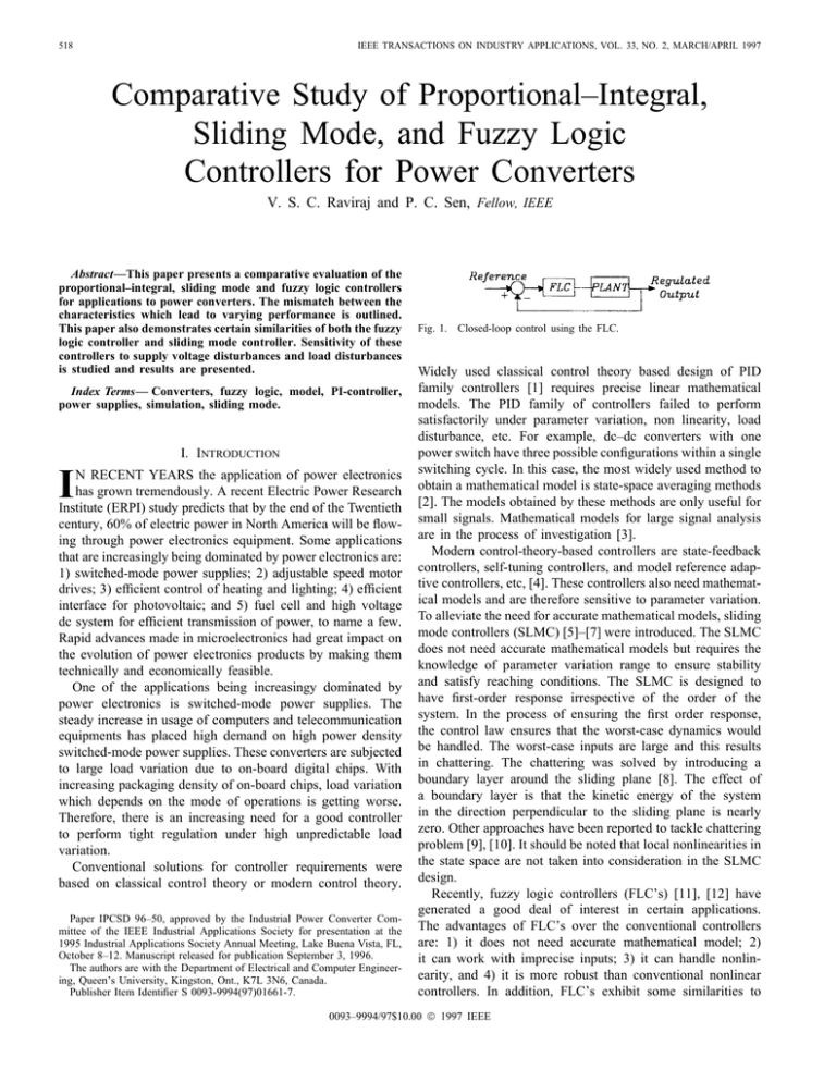
518 IEEE TRANSACTIONS ON INDUSTRY APPLICATIONS, VOL. 33, NO. 2, MARCH/APRIL 1997 Comparative Study of Proportional–Integral, Sliding Mode, and Fuzzy Logic Controllers for Power Converters V. S. C. Raviraj and P. C. Sen, Fellow, IEEE Abstract—This paper presents a comparative evaluation of the proportional–integral, sliding mode and fuzzy logic controllers for applications to power converters. The mismatch between the characteristics which lead to varying performance is outlined. This paper also demonstrates certain similarities of both the fuzzy logic controller and sliding mode controller. Sensitivity of these controllers to supply voltage disturbances and load disturbances is studied and results are presented. Index Terms— Converters, fuzzy logic, model, PI-controller, power supplies, simulation, sliding mode. I. INTRODUCTION I N RECENT YEARS the application of power electronics has grown tremendously. A recent Electric Power Research Institute (ERPI) study predicts that by the end of the Twentieth century, 60% of electric power in North America will be flowing through power electronics equipment. Some applications that are increasingly being dominated by power electronics are: 1) switched-mode power supplies; 2) adjustable speed motor drives; 3) efficient control of heating and lighting; 4) efficient interface for photovoltaic; and 5) fuel cell and high voltage dc system for efficient transmission of power, to name a few. Rapid advances made in microelectronics had great impact on the evolution of power electronics products by making them technically and economically feasible. One of the applications being increasingy dominated by power electronics is switched-mode power supplies. The steady increase in usage of computers and telecommunication equipments has placed high demand on high power density switched-mode power supplies. These converters are subjected to large load variation due to on-board digital chips. With increasing packaging density of on-board chips, load variation which depends on the mode of operations is getting worse. Therefore, there is an increasing need for a good controller to perform tight regulation under high unpredictable load variation. Conventional solutions for controller requirements were based on classical control theory or modern control theory. Paper IPCSD 96–50, approved by the Industrial Power Converter Committee of the IEEE Industrial Applications Society for presentation at the 1995 Industrial Applications Society Annual Meeting, Lake Buena Vista, FL, October 8–12. Manuscript released for publication September 3, 1996. The authors are with the Department of Electrical and Computer Engineering, Queen’s University, Kingston, Ont., K7L 3N6, Canada. Publisher Item Identifier S 0093-9994(97)01661-7. Fig. 1. Closed-loop control using the FLC. Widely used classical control theory based design of PID family controllers [1] requires precise linear mathematical models. The PID family of controllers failed to perform satisfactorily under parameter variation, non linearity, load disturbance, etc. For example, dc–dc converters with one power switch have three possible configurations within a single switching cycle. In this case, the most widely used method to obtain a mathematical model is state-space averaging methods [2]. The models obtained by these methods are only useful for small signals. Mathematical models for large signal analysis are in the process of investigation [3]. Modern control-theory-based controllers are state-feedback controllers, self-tuning controllers, and model reference adaptive controllers, etc, [4]. These controllers also need mathematical models and are therefore sensitive to parameter variation. To alleviate the need for accurate mathematical models, sliding mode controllers (SLMC) [5]–[7] were introduced. The SLMC does not need accurate mathematical models but requires the knowledge of parameter variation range to ensure stability and satisfy reaching conditions. The SLMC is designed to have first-order response irrespective of the order of the system. In the process of ensuring the first order response, the control law ensures that the worst-case dynamics would be handled. The worst-case inputs are large and this results in chattering. The chattering was solved by introducing a boundary layer around the sliding plane [8]. The effect of a boundary layer is that the kinetic energy of the system in the direction perpendicular to the sliding plane is nearly zero. Other approaches have been reported to tackle chattering problem [9], [10]. It should be noted that local nonlinearities in the state space are not taken into consideration in the SLMC design. Recently, fuzzy logic controllers (FLC’s) [11], [12] have generated a good deal of interest in certain applications. The advantages of FLC’s over the conventional controllers are: 1) it does not need accurate mathematical model; 2) it can work with imprecise inputs; 3) it can handle nonlinearity, and 4) it is more robust than conventional nonlinear controllers. In addition, FLC’s exhibit some similarities to 0093–9994/97$10.00 1997 IEEE RAVIRAJ AND SEN: STUDY OF PROPORTIONAL–INTEGRAL, SLIDING MODE, AND FUZZY LOGIC CONTROLLERS 519 Fig. 2. Internal Structure of FLC and closed-loop control of Buck converter. SLMC. This is obvious from the typical rule table of the FLC. Unlike SLMC, it is possible to take account for local nonlinearities in FLC. So far, FLC’s in power electronics have been designed by trial and error. Power converters are inherenty nonlinear. The causes of nonlinearity in the power converters include a variable structure within a single switching period, saturating inductances, voltage clamping, etc. With the advent of resonant converters, power converters are getting complicated, resulting in complex mathematical models. The FLC seems to be a viable controller for power electronic applications. This paper explores the potential and feasibility of FLC control for power electronic circuits. A Buck converter is considered to exhibit that satisfactory voltage regulation can be achieved without having to obtain complicated mathematical models for large signals or having to estimate the range of parameter variation. Simulation results are presented to explore the potentials of FLC for applications to power electronic circuits. To emphasize the merits and demerits of the FLC, some comparisons have also been made with the proportional–integral (PI)-controller and the SLMC controller under load and supply disturbances. Fig. 3. Membership functions used for fuzzification and defuzzification. II. FUNDAMENTALS OF FUZZY LOGIC CONTROL Fuzzy logic control is a new addition to control theory. Its design philosophy deviates from all the previous methods by accommodating expert knowledge in controller design. Fuzzy logic control is derived from fuzzy set theory introduced by Zadeh in 1965 [13]. In fuzzy set theory, the transition between membership and nonmembership can be gradual. Therefore, boundaries of fuzzy sets can be vague and ambiguous, making it useful for approximate systems. FLC’s are an attractive choice when precise mathematical formulations are not possible. Other advantages of FLC are: 1) it can work with less precise inputs; 2) it doesn’t need fast processors; 3) it needs less data storage in the form of membership functions and rules than conventional look up table for nonlinear controllers; and 4) it is more robust than other nonlinear controllers. Fig. 4. Defuzzification using center of gravity method. The schematic diagram of a closed loop fuzzy controller is shown in Fig. 1. A reference input is compared with the regulated output to produce an error. The error is fed to the FLC, which performs calculations to generate output. This is called the fuzzy inference process and requires three basic steps as illustrated in the next section. The schematic diagram of a closed-loop FLC for a Buck converter is shown in Fig 2. The FLC has three functional blocks for calculation and two databases. The functional blocks in FLC are: 1) fuzzifier; 2) rule evaluator; and 3) defuzzifier. The two databases are Rulebase and Database. Functions of these five components are described in the following sections. 520 IEEE TRANSACTIONS ON INDUSTRY APPLICATIONS, VOL. 33, NO. 2, MARCH/APRIL 1997 Fig. 5. Rule table. III. FUZZIER Fuzzy logic uses linguistic variables instead of numerical variables. In a closed loop control system, error between reference and output can be labeled as zero (Z), positive small (PS), negative small (NS), etc. In real world, measured quantities are real numbers (crisp). The process of converting a numerical variable (real number) into a linguistic variable (fuzzy number) is called fuzzification. Fig. 3 shows the triangular membership function used in fuzzification. For a given crisp input, fuzzifier finds the degree of membership in every linguistic variable. Since there are only two overlapping memberships in this specific case, all linguistic variables except two will have zero membership. IV. RULE EVALUATOR (DECISION MAKING) In conventional controllers, we have control gains or control laws which are combination of numerical values. In FLC, the equivalent term is rules and they are linguistic in nature. A typical rule can be written as follows. : If is and CE is then output is Where are the labels of linguistic variables of Error (E), Change of Error (CE) and output respectively. E, CE and output respresent degree of membership To evaluate the above rule fuzzy set theory is used Fuzzy Set Let be a collection of objects denoted generically by , which could be discrete or continuous, is called the universe. If an element in the universe, say , is a member of then mapping is given as fuzzy set RAVIRAJ AND SEN: STUDY OF PROPORTIONAL–INTEGRAL, SLIDING MODE, AND FUZZY LOGIC CONTROLLERS 521 The basic fuzzy set operations needed for evaluation of fuzzy rules are AND OR and NOT 1) AND Intersection: 2) OR Union: 3) NOT Complement By definition of AND, evaluation of rule results in a allocated to minimum of V. DEFUZZIFICATION The reverse of fuzzification is called defuzzification. The rules of FLC produce required output in a linguistic variable (Fuzzy Number). According to real world requirements, linguistic variables have to be transformed to crisp output (Real number). The choices available for defuzzification are numerous. So far the choice of strategy is a compromise between accuracy and computational intensity. In the present paper, the center of gravity method [14], as shown in Fig 4, has been used. The linguistic output variable from the rule evaluator and definition of output membership are used to calculate the shaded area. Finally, crisp output is obtained by using Fig. 6. Buck converter and closed loop control. Output VI. DATABASE The Database stores the definition of the membership function required by fuzzifier and defuzzifier. Storage format is a compromise between available memory and MIPS of the digital controller chip. VII. RULEBASE The Rulebase stores the linguistic control rules required by rule evaluator (decision making logic). Fig 5 shows the rule table used in this paper. VIII. SIMULATION RESULTS The Buck converter considered for study is shown in Fig 6. All PID controllers have their equivalent variable gain fuzzy PID. In terms of mathematical symbol, they could be written as follows: Fuzzy PD: Fuzzy PI: Fuzzy PID: Even though the symbolic representation is same as conventional PID’s, in the case of fuzzy PID’s gain varies depending on operating point. Fuzzy PD like conventional PD has steady state error. Fuzzy PID needs acceleration of error. Measuring or estimating acceleration terms are difficult and inaccurate. Hence Fuzzy PID has implementation problem. Due to the above-mentioned disadvantages with PD and PID, Fuzzy PI is chosen for this paper. Fig. 7. FLC response for load disturbance (V0 (ref ) = 10 V). Fig 7 shows the regulated voltage response for load variation of 2.5 to 5 to 2.5 . Regulated voltage shows small overshoot and undershoot at the transition without any oscillation. Fig 8 shows the regulated voltage response for supply voltage variation of 20 V to 15 V to 25 V. Regulated voltage shows very small overshoot and it settled down quickly. IX. COMPARISON WITH PROPORTIONAL INTEGRAL (PI) AND SLIDING MODE CONTROLLER (SLMC) To assess the viability of FLC, it is appropriate at this stage to compare the performance of FLC with other standard controllers. PI and, more recently, SLMC has been used in industry. The performance of PI and SLMC are presented in this section and they are compared with FLC performances presented in the previous section. The same disturbances are applied to PI and SLMC, so that any comparison is justifiable. X. PROPORTIONAL-INTEGRAL (PI) CONTROLLER PI controllers have been in use for the last few decades. They perform satisfactorily during transient under limited operating range. Also steady state performance is excellent. Implementation in analog or digital hardware is inexpensive 522 IEEE TRANSACTIONS ON INDUSTRY APPLICATIONS, VOL. 33, NO. 2, MARCH/APRIL 1997 Fig. 8. FLC response for supply disturbance (V0 (ref ) = 10 V). Fig. 9. Closed-loop control using PI controller. Fig. 11. PI response for supply disturbance (V0 (ref) = 10 V). (a) (b) Fig. 12. SLMC. (a) Closed-loop system. (b) Phase plane trajectory. Fig. 10. PI response for load disturbance (V0 (ref) = 10 V). and straight forward. Since the PI controller is based on a linear model, response for large signal disturbance is poor. As and are constants and they shown in Fig 9, the gains are fine tuned for specific operating condition. Fig. 10 shows the regulated voltage response for load variation of 2.5 to to 2.5 Regulated voltage shows small overshoot and 5 under damped oscillation. Fig. 11 shows the regulated voltage response for supply voltage variation of 20 V to 15 V to 25 V. Regulated voltage shows appreciable overshoot and it settles down slowly compared to FLC. XI. SLIDDING MODE CONTROLLER (SLMC) In recent times, the SLMC has shown the potential to be insensitive to parameter variations and external disturbances. A closed-loop control system using SLMC is shown in Fig. 12(a). In SLMC, the system response in the phase plane is forced to follow a sliding line as shown in Fig. 12(b), denotes the state error which needs to be driven to zero and is its derivative. In the time domain, the corresponding response is exponential. This response depends only on the . slope of the sliding line Fig. 13 shows the regulated voltage response for load variation of 2.5 to 5 to 2.5 . Regulated voltage shows very small overshoot and settles down in a highly damped mode. But it has a steady state error. Fig. 14 shows the regulated voltage response for supply voltage variation of 20 V to 15 V to 25 V. Regulated voltage shows small overshoot and it settles down quickly to a steady state with a steady-state error. XII. COMPARISON The controllers for IP, SLMC, and FLC were designed to regulate the output voltage under supply voltage disturbances and load disturbances. The design of FLC is primarily based on a trial and error procedure. The triangular membership was considered because of its simplicity of implementation and because less computational intensity is required. The number of linguistic variables and the base width of linguistic variables have some effect on the response time and magnitude of ripple RAVIRAJ AND SEN: STUDY OF PROPORTIONAL–INTEGRAL, SLIDING MODE, AND FUZZY LOGIC CONTROLLERS Fig. 13. 523 SLMC response for load disturbance (V0 (ref ) = 10 V). Fig. 15. FLC, PI and SLMC phase plane trajectory for startup. where as SLMC has a non zero steady state error. This steady state error is due to PD feedback which needs an error to produce a nonzero control to keep the steady state. During load disturbance FLC performs satisfactorily during the transient, as well as the steady state. For supply disturbance, FLC and SLMC respond in a highly damped manner with a small overshoot whereas PI responds in an under damped manner with very high overshoot. At steady state FLC and PI have almost zero steady-state error where as SLMC has a non zero steady-state error. During supply disturbance FLC out performs PI and SLMC during transient, as well as the steady state. Fig. 14. SLMC response for supply disturbance (V0 (ref) = 10 V). in the output voltage. However, they don’t seriously affect the response as the change of gains in a PI controller does. The seven linguistic variables with equal basewidth gave satisfactory results for output voltage regulation. In the design for SLMC, the PD-type feedback was considered because it is supposed to produce steady state error with reduced chattering (i.e., ripple voltage). The on-off control could have been added to avoid steady-state error but it would have produced more ripple voltage. In the design of the PI-controller, the gain selection is crucial. A set of gains can be ideal for one type of disturbance but not for another type of disturbance. The gains were selected to provide a performance compromise for supply voltage disturbance and load disturbance. Digital implementation at the sampling rate of 20 kHz was considered for all these controllers. From the results shown in Figs 7, 8, 10, 11, 13 and 14, for load change FLC and SLMC respond to a highly damped manner whereas PI respond in an under damped manner. At steady state FLC and PI have almost zero steady state error XIII. SIMILARITY BETWEEN FLC AND SLMC Fig. 15 shows the phase plane startup response of FLC, SLMC, and PI. Both FLC and SLMC have a similar trajectory with different slope. In SLMC, the slope could be chosen as a design parameter. In FLC, the slope of the sliding line is decided by definition of linguistic variables (membership functions). There is no straightforward method to choose linguistic variables to have a required time constant. In the case of FLC, the sliding line is not linear as it is in the case of SLMC. XIV. CONCLUSIONS The study of fuzzy logic control, PI control, and SLMC suggest that FLC performs satisfactorily in regulating the output during external disturbances. The transient overshoot in FLC is negligible compared to PI response. The control law employed in SLMC inherently has steady-state error due to PD type of feedback. PI shows under damped response during disturbances due to off-tuned gain constants. FLC shows sliding-mode characteristics of SLMC. From the present study, FLC seems to be a viable controller for application in power electronic systems. 524 IEEE TRANSACTIONS ON INDUSTRY APPLICATIONS, VOL. 33, NO. 2, MARCH/APRIL 1997 REFERENCES [1] P. K. Nandam and P. C. Sen, “A comparative study of proportionalntegral proportional controllers for DC motor drives,” Int. J. Contr., vol. 44, no. 1, pp. 283–297, 1986. [2] R. D. Middlebrook and S. Cuk, “A general unified approach to modeling switching converter power stages,” Int. J. Electron., 1977, vol. 42, no 6, pp. 521–550, 1977. [3] Y. F. Liu and P. C. Sen, “A general unified large-signal model for current programmed DC-to-DC converters,” IEEE Trans. Power Electron., vol. 9, pp. 414–424, 1994. [4] P. C. Sen, “Electric motor drives and Control—Past, present, and future,” IEEE Trans. Ind. Electron., vol. 37, pp. 562–575, Dec. 1990. [5] C. Namuduri and P. S. Sen, “A servo-control system using a selfcontrolled synchronous motor with sliding mode controller,” IEEE Trans. Industry Applicat., vol. IA-23, pp. 283–295, Mar./Apr. 1987. [6] B. K. Bose, “Sliding model control of induction motor,” in IEEE-IAS Conf. Rec. 1985, pp. 479–486. [7] R. Venkataramanan and A. Sabanovic and S. Cuk, “Sliding mode control of DC–DC converters,” in IEEE–IECON Rec., 1985, pp. 251–258. [8] J. E. Slotline and W. Li, Applied Nonlinear Control. Englewood Cliffs, NJ: Prentice-Hall, 1991. [9] E. E. Y. Ho and P. C. Sen, “Control dynamics of speed drive systems using sliding mode controllers with integral compensation,” IEEE Trans. Ind. Applicat., vol. 27, pp. 883–892, Sept./Oct. 1991. [10] E. E. Y. Ho, and P. C. Sen, “A High-performance parameter-insensitive drive using a series-connected wound rotor induction motor,” IEEE Trans. Ind. Applicat., vol. 25, pp. 1132–1138, Nov./Dec. 1989. [11] W. C. So, C. K. Tse, and Y. S. Lee, “A fuzzy controller for DC–DC fonverters,” in IEEE PESC Conf. Rec., 1994, pp. 315–320. [12] C. C. Lee, “Fuzzy logic in control systems: Fuzzy logic controller—Parts I and II,” IEEE Trans. Syst., Man, Cybern., vol. 20, pp. 404–435, Apr. 1990. [13] L. A. Zadeh, “Fuzzy sets,” Inform. Contr., vol. 8, pp. 338–353, 1965. [14] D. Driankov, H. Hellendoorn, and M. Reinfrank, An Introduction to Fuzzy Control. New York: Springer-Verlag, 1993. V. S. C. Raviraj received the B.E. (Hons.) degree in electrical and electronics engineering from Madurai Kamaraj University, Tamil Nadu, India, in 1988, and the M.Engg. degree in electrical engineering from the University of New Orleans, Baton Rouge, in 1993. He is presently working toward the Ph.D. degree at the Department of Electrical and Computer Engineering, Queen’s University, Ont., Canada. His research interest is in the application of fuzzy logic control and neural network control in power electronics and drive systems. Paresh C. Sen (M’67–SM’74–F’89) was born in Chittagong, Bangladesh. He received the B.Sc. degree (Hons.) in physics and the M.Sc. degree (Tech.) in applied physics from the University of Calcutta, India, in 1958 and 1961, respectively, and the M.A.Sc. and the Ph.D. degrees in electrical engineering from the University of Toronto, Ont., Canada, in 1965 and 1967, respectively. He is Professor of Electrical Engineering at Queen’s University, Ont., Canada. He has written more than 100 research papers in the general area of power electronics and drives. He is the author of two books—Thyristor DC Drives (New York: Wiley, 1981) and Principles of Electric Machines and Power Electronics (New York: Wiley, 1988). His fields of interest include power electronics and drives, microcomputer control of electric drives systems, modern control techniques for high-performance drive systems, and switching power supplies. Dr. Sen has served on program committees of many IEEE and international conferences and has organized and chaired many technical sessions. He has served as Associate Editor of IEEE TRANSACTIONS ON INDUSTRIAL ELECTRONICS AND CONTROL INSTRUMENTATION (Industrial Electronics Society), as chairman of the technical Committees on Power Electronics (1979–1980) and Energy Systems (1980–1982). At present, he is an active member of the Industrial Drives Committee and the Industrial Power Converter Committee of the IEEE Industry Applications Society. He is also a member of the International Steering Committee on International Conference on Electric Drives (ICED). He is internationally recognized as a specialist in power electronics and drives and has received a Prize Paper Award from the Industrial Drive Committee for technical excellence at the Industry Applications Society Annual Meeting in 1986.
