Gree Free Match Cozy GWH Ind Maintenance and Faults
advertisement
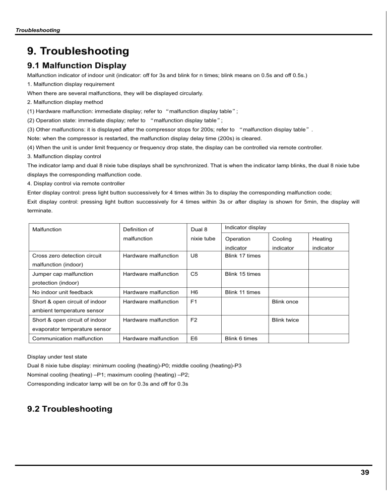
Troubleshooting 9. Troubleshooting 9.1 Malfunction Display Malfunction indicator of indoor unit (indicator: off for 3s and blink for n times; blink means on 0.5s and off 0.5s.) 1. Malfunction display requirement When there are several malfunctions, they will be displayed circularly. 2. Malfunction display method (1) Hardware malfunction: immediate display; refer to Āmalfunction display tableā; (2) Operation state: immediate display; refer to Āmalfunction display tableā; (3) Other malfunctions: it is displayed after the compressor stops for 200s; refer to Āmalfunction display tableā. Note: when the compressor is restarted, the malfunction display delay time (200s) is cleared. (4) When the unit is under limit frequency or frequency drop state, the display can be controlled via remote controller. 3. Malfunction display control The indicator lamp and dual 8 nixie tube displays shall be synchronized. That is when the indicator lamp blinks, the dual 8 nixie tube displays the corresponding malfunction code. 4. Display control via remote controller Enter display control: press light button successively for 4 times within 3s to display the corresponding malfunction code; Exit display control: pressing light button successively for 4 times within 3s or after display is shown for 5min, the display will terminate. Definition of Dual 8 Indicator display malfunction nixie tube Operation Cooling Heating indicator U8 indicator Blink 17 times indicator Hardware malfunction Hardware malfunction C5 Blink 15 times No indoor unit feedback Hardware malfunction H6 Blink 11 times Short & open circuit of indoor Hardware malfunction F1 Blink once Hardware malfunction F2 Blink twice Hardware malfunction E6 Malfunction Cross zero detection circuit malfunction (indoor) Jumper cap malfunction protection (indoor) ambient temperature sensor Short & open circuit of indoor evaporator temperature sensor Communication malfunction Blink 6 times Display under test state Dual 8 nixie tube display: minimum cooling (heating)-P0; middle cooling (heating)-P3 Nominal cooling (heating) –P1; maximum cooling (heating) –P2; Corresponding indicator lamp will be on for 0.3s and off for 0.3s 9.2 Troubleshooting 39 Troubleshooting 9.2.1 F1/F2 malfunction Star Is the wiring terminal between temperature sensor and the controller loosened or poo rly contacted? yes Insert the temperature sensor tightly no no Is there short circuit due to tri-pover of the pa rts? Malfunction is eliminated. yes Make the parts upright no no Is the temperature sensor normal according to the Resistance Table? Malfunction is eliminated. yes no Replace it with a temperature sensor of the same model yes no Malfunction is removed. Replace the controller with one of the same model yes End 40 yes Troubleshooting 9.2.2 H6 malfunction Possible causes:1.Fan motor is locked; 2.The feedback terminal of PG motor is not connected tightly; 3.The control terminal of PG motor is not connected tightly; 4.Motor is damaged; 5.Malfunction of the rotation speed detection circuit of the mainboard.See the flow chart below: “ H6 ” is displayed on the unit. Stir the fan blade with a hand when the unit is DEENERGIZED. Does the blade rotate unsmoothly ? Yes Is the malfunction eliminated ? No No Is the feedback terminal of PG motor loose? No Yes Insert the feedback terminal tightly . Is the malfunction eliminated? No Is the control terminal of PG motor loose? Reinstall the motor and the blade to make it rotate smoothly . Yes Yes Insert the control terminal tightly . Yes Is the malfunction eliminated? No No Re-energize to turn on the unit;measure within 1 turn on the unit;measure within 1 min after the louvers are opened whether Yes the output voltage on the control terminal of the PG motor is over 50V No No Mainboard malfunction ; Replace it . Yes Replace the fan motor . Is the malfunction eliminated? Yes End 41 Troubleshooting 9.2.3 C5 malfunction Possible causes:1.There is no jumper cap on the controller;2.Jumper cap is not inserted properly and tightly;3.Jumper cap is damaged;4. Controller is damaged.See the flow chart below: C5 is displayed on the unit. Is there jumper cap on the controller ? Yes No Install a matching jumper cap . Is the malfunction eliminated? No Is the jumper cap inserted incorrectly or improperly? No No Yes Re-insert the jumper cap. Is the malfunction eliminated Yes Replace the jumper cap. Is the malfunction eliminated? Yes Yes No The mainboard is defined abnormal replace it. End 42 Troubleshooting 9.2.4 U8 malfunction Possible causes; 1.The controller diagnoses incorrectly due to instant energization after de-energized while the capacitor discharges slowly; 2.Malfunction of the zero-cross detection circuit of the mainboard. See the flow chart below: “ U8 ” is displayed on the unit. Re-energize1 minute after de-erergization Is “U8” still displayed ? No The unit returns to normal. Conclusion: U8 is displayed due to instant energization afte deenergization while the capacitor discharges slowly. Yes The zero-cross detection circuit of the mainboard is defined abnormal. Replace the mainboard. Malfunction is eliminated. 43 Troubleshooting 9.2.5 E6 malfunction Inspection Check if connection wire between indoor and outdoor units and wire inside the unit are connected well. Check if mainboard of indoor or outdoor unit is damaged Flowchart Communication malfunction of some indoor units De-energize the unit and check if the connecting wire of indoor and outdoor unit and wiring of electric box are correct. Is wire connected No Connect wires according to the correctly˛ removed˛ wiring diagram No Yes De-energize the unit. Change the communication cable of indoor units. Energize the unit and wait for 3 min Does the broken-down indoor unit resume normal? No Replace the broken-down mainboard of the indoor unit End 44 Is malfunction Yes Replace mainboard of outdoor unit Yes Troubleshooting Communication malfunction of all indoor units De-energize the unit and check if the connecting wire of indoor and outdoor unit and wiring of electric box are correct. No Is wire connected Connect wires according to the correctly˛ wiring diagram Yes Is malfunction removed˛ No Yes De-energize the unit. Check if the connecting wire between outdoor mainbaord and filter plate is correct. Is wire connected Connect wires No according to the correctly˛ wiring diagram Yes Is malfunction removed˛ No Yes Is connecting wire Yes damaged˛ Replace the Is malfunction connecting wire removed˛ Yes No No Check if there is power input between neutral wire and live wire of outdoor unit. Is there power No input? Replace filter plate of Is malfunction outdoor unit removed˛ Yes No Yes Replace mainboard of outdoor unit Does communication resume normal˛ No Replace mainboard of indoor unit Yes End Note: The information above is for reference only. 45
