Daniel Lancelot. ,4? ATTORNEY
advertisement
Sept. 29, 1953
D, LANCELOT
'
2,654,074
MULTIPLE ELECTRIC PLUG RECEPTACLE
Filed Oct. 7, 1950
‘
INVENTOR.
Daniel Lancelot.
,4? ATTORNEY;
Patented Sept. 29, 1.953
2,654,074
UNITED STATES PATENT‘ OFFICE
2,654,074
MULTIPLE ELECTRIC PLUG RECEPTACLE
Daniel Lancelot, Pittsburgh, Pa.
Application October 7, 1950, Serial No. 189,005
4 Claims. (01. 339-76)
1
This invention relates generally to electrical
plug receptacles and more in particular to a plug
receptacle which may be plugged into a standard
?ush mounted plug receptacle forming a perma
nent part of the wiring of a building.
Numerous variations of plug-in types of plug
receptacles are available for multiplying plug-in
facilities at a particular plug receptacle. In
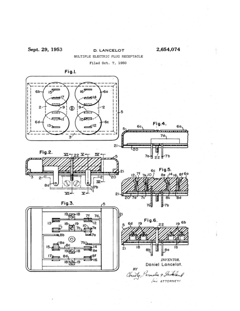
plug-in plug receptacle of Fig. 1;
most of these, the plug-in receptacle comprises
spectively, of Fig. 2.
receptacle embodying the principles of this in
vention;
Fig. 2 is a longitudinal sectional view of the
Fig. 3 is a bottom plan view of the plug-in plug
receptacle of Fig. 1; and
Figs. 4, 5 and 6 are, respectively, sectional views
taken on the lines IV-IV, V—V and VI—-VI, re
.
a housing of electrical insulating material having 10
The several illustrations of the drawing illus
plug receptacles, in several of the faces thereof,
trate a preferred embodiment of this invention
connected to a pair of protruding prongs adapted
designed for plug-in connection to a standard
to plug into a standard ?ush mounted receptacle.
double ?ush mounted plug receptacle of the type
Usually three, and sometimes more, plug recep
permanently wired into a wiring system. These
15
tacles are provided in the faces of the plug-in
standard plug receptacles are usually placed in a
unit. Thus the facilities of a single outlet, by
wall of a building, in keeping with the electrical
such an expedient, are increased at least three
code, and are mounted in metal boxes, secured
fold. Thus a concentration, for example, of
to the building frame in such a position that the
household electrical devices such as appliances
edges de?ning the open end of the box are sub
and portable lighting units may be conveniently
stantially at the ?nished surface of the wall.
handled.
Such a box is not shown in the interest of sim
The mechanics of such an arrangement how
plicity. The standard plug receptacle is ?tted
ever, are poor. The entire mechanical load hangs
into the box and secured thereto by means of
on the prongs of the plug-in plug receptacle and
screws (not shown). In the case of a double
after a short period of time, mechanical failure
plug receptacle, as l (or duplex convenience out
of the ?ush mounted plug receptacle occurs.
let as it is sometimes known), when mounted in
,Since this last-named receptacle is essentially, a
the box, each plug receptacle face 2 protrudes
permanent part of the wiring system, its replace
about one-eighth of an inch beyond the wall
ment is a matter of some consequence. Plug-in
surface. A cover plate 3 of rectangular plan
receptacles of this type, therefore, do not repre
forming having a pair of openings therein neatly
sent an adequate solution to the problem.
?tting about the edges of the faces of the plug
One object of this invention is to provide a
receptacles covers the box opening and seats
plug-in type of plug receptacle which may be
against the wall. In practice, a cover plate
securely mechanically attached to a standard
mounting screw clears through the cover plate
?ush mounted plug receptacle forming a perma
and threads into a threaded hole in the plug re
nent part of a wiring system.
ceptacle between the plug receptacle faces to se
More in particular it is an object of this inven
cure the cover plate in position. Alternatively
tion to provide a plug-in type of plug receptacle
some standard receptacles may require the use:
having two pairs of plug connectors for plug-in
of two screws in mounting the cover plate.
connection with a standard double plug recep
The present invention contemplates establishtacle of the ?ush mounted type wherein provi
ing electrical connections in the two plug recep
sion is had for securely mechanically attaching
tacles of a standard double plug receptacle, for a.
the plug-in plug receptacle to the standard plug
plurality of plug receptacles in a single insulating
receptacle.
block and securing'the assembly in position by a.
It is also an object of this invention to provide
screw or screws as required clearing through the
plug-in plug receptacles of the character re
plug receptacle block and threadedly engaging
ferred to in the preceding objects with a plu
the threaded hole in the standard double plug
rality of plug receptacles therein.
receptacle.
’
The foregoing statements are merely illustra
In Figs. 1, 2 and 3, the insulating receptacle
tive of the various aims and objects of this in 50 base or housing is designated 5 and is provided
vention. Other objects and advantages will be
with four plug receptacles 6a, 6b, 6c and 6d which
come apparent upon a study of the following-dis
are grouped in pairs on opposite sides of alongi
closure when considered in conjunction with the
tudinal center line through the base. In Fig. 1,
accompanying drawing, in which:
the position of the standard double plug recep
Fig. 1 is a plan view of a plug-in type of plug 55 ‘tacle is indicated by the individual plug recep
2,654,074
3
4
connections may be extended to include any
standard receptacle cover plate 3 is also indi
cated in dotted outline. As will be seen from the
bottom view of Fig. 3, the plug-in type of plug
receptacle of this invention is provided with two
pairs of plug prongs ‘la, ‘lb and 8a, 8b, respec
tively, which are suitably spaced along the base
in correspondence with the spacing of the prong
receiving openings 9 01' the standard double plug
receptacle I.
'
'
.
illustrated, it will be appreciated that the parallel
tacle 2', in dotted outline, and the position of the
number of plug receptacles within practical lim
its. Although the present design has been made
to straddle the cover plate 3 for the standard re
ceptacle I so that the cover plate need not be
removed, it will be appreciated that other designs
may be made which are exactly the size of the
10
The prongs 1a, 1b, 8a and 8b may be an integral
standard double receptacle cover plate, removal
of the cover plate being optional. In any event.
the unit is preferably of such a size as to com
pletely cover the standard receptacle and its
mounting box as does the standard cover plate.
part of, or otherwise suitably joined to, a plurality
of current carrying strips secured in suitable
It will be appreciated that numerous variations
connections to the respective plug receptacles ‘6a 15 in ~design details with regard to the con?guration
of parts'ahd the location of the plug receptacles
through 6d. To this end, prong la is integrally
oi
plugein ~?xture may be had without de
formed with strip ‘(c which egtends between the
cavities in the insulating basc 5 to prgvide circuit
parting ‘from the spirit and scope of this inven
prong-receiving openings [0 and H of the plug
tion. Accordingly, it is intended that the fore
receptacles 6c and 611, respectively. Prong 1b is
an integral part of a u-shaped metal strip 1d, 20 going disclosure and the illustrations of the
being formed at the the of the shed leg thereaf
drawings shall be considered only as illustrative
“Pound the Pl?“ 1‘?
{$11.9 1W8 léig 0f the
U-shaped member straddles the prpngerepeiying
’1 claim:
1. An electrical convenience outlet unit for at
95th? mil-9.1.9165 hi this invention
The ‘ bi'glit of the’ U-shaped strip 1d extends
openings .1? and '13 9f P1145 receptacles 6? and 5d,
25
tachment to a standard builtfin, flush mounted,
convenience outlet having two conventional plug
receptacles and at least one threaded hole for
receiving a cover plate mounting screw, compris
ing, in combination, a base of electrical insulating
I2 adjacent one side thereof (see Fig. 5‘) to slid
sbly engage the prongs 0? a sthhdard plug @011 30' material, two pairs of metal bayonet prongs ?tted
and secured in said base in positions to plug into
n?ctol‘ to .be plugged WQ'QP- lirehgereeeivins
the two conventional plug receptacles, respec
openings II and ‘I’; have similar contact strips
respectively. Contact strips ‘bio and ‘if, which
may be an integral Part of ships 7!; and 1d. re
speh?vely, Project upwardly hit? epehinss 1? and
tiveiy; a metal strip connected to one prong of
one of said pairs of prongs and secured in said
(not shown), integrally formed with strips 1,0 and
1.11, ?tted therein. $t'rips t9 eh? Pd, renewed
ing, respectively to strips 1? and .ld, are integrally
35
formed with prongs .811 ehd {lb and each is pre
vided with contact strips projecting into prong
receiving openings “[15; i6 and 11. Contact
strips Bev and 8/‘ which are integrally iorrned with
strips _8c and 8d are shown in Fig. ‘5 intheir re
spective positions in érohg-reeeivihg ol?mllgs, U
and 1.6 .of plug receptacle ta. [l‘ihis construction
whhecis 151118" receptacles W .hhd B1? in parallel
and connects. P1148 r§9¢PP§i°1¢S 5c @4115 W in Paral
lel. doubling the Plus receptacle capacity of the
standard double plug receptacle 1.
As earlier
‘
cf the strips ‘[0, 1d and
8c, 8d are disposed in suitable cavities in the
base or housing.§. $uitable means for securing
these strips in the base is represented in the
mounting'tabs l8 integrally formed with the re,
spective strips
secured to the base by screws
f9 which clear therethrough and threaded-1y en
gage the base. The details of this mounting ap:
base, a second metal strip corresponding to the
?rst-mentioned metal strip secured to a prong .of
the other pair of prongs positioned diagonally op~
posite said ?rstementioned prong, said second
metal strip being secured in said base in a
40
45
position substantially paralleling and oppo
site to said ?rst-mentioned metal strip, metal
strips connected to the remaining prong of each
pair of prongs and secured in said base in paral
lel spaced relation with the metal strip connected
to the other prong of that pair forming spaced
pairs of metal strips, said base having spaced
pairs ‘of openings therethrough into said spaced
pairs of metal strips for permitting the entrance
ofthe prongs ,of standard electrical plugs into en
5,0 gagement-with the respective pairs-of metal strips,
whereby a plurality of parallel connections is at
forded with each pair of metal strips, and a
mounting screw clearing through said base and
adapted to engage the threaded ‘hole in the stand
bottom of this plug-in 55 ard convenience .outletto secure said base over the
pear in Figs. 3 ‘and 6.
type of Plug receptacle is covered with a sheet of
material of electrical insulating material ‘29 (not
standard convenience outlet.
2.
'
electrical convenience outlet .unit for at
shown in
3) to insnlatedly enclose the metal
strips ‘Ic, 1d, 8c and go.
la, 1b, 8a .and 81)
tachrnent to a standard built-in, ?ush mounted,
convenience outlet having two conventional plug
project through suitable openings in this sheet 20.
In the illustrated embodiment -_a marginal skirt
receptacles and at least‘ one threaded hole for
receiving a'cover plate mounting screw, compris
ing, ‘in combination, a base of electrical insulat
ing material, two pairs .of metal bayonet prongs
2| is provided, the bottom edges of which engage
the finished wall surface and space the unit a
su?icient distance from the wall surface to clear
?tted and secured in said base in positions to
the faces of plug receptacles 2 .of the standard
plug into the two conventional plug receptacles,
double plug receptacle. The unit is securely
mounted .to the standard plug receptacle _4 by a
respectively; a metal strip connected to one prong
of one of said pairs of .prongs and secured in
screw 22 which‘ clears through the insulating base
said base, a second metal strip corresponding to
the ?rst-mentioned metal strip secured to a
or how 5 has thmhsls-ihtothethrehdedho1e
in standard plug rcqeptacle l which normally rev 70 prong of the other pair of prongs located in a
position diagonally opposite said ?rst-mentioned
ceives the ‘cover plate ‘screw. affording a strong
mechanical connection completely relieuing the
prongs in the plug receptacle in through 5d of
prong, said second metal strip being secured in
said base in a position substantially parallelling
and opposite to said ?rst-mentioned meal strip,
mechanical load.
‘
While We Page 9; 19.1115 reqeptacles have been 75 metal strips connected to the remaining prong
2,054,074
5
6
of each pair of prongs and secured in said base
in parallel spaced relation with the metal strip
connected to the other prong of 'that pair forming
spaced pairs of metal strips, said base having
spaced pairs of openings therethrough into said
ard convenience outlet to secure said base over
standard convenience outlet to secure said base
over said standard convenience outlet, said base
one of said pairs of prongs and secured in said.
base, a second metal strip corresponding to the
?rst-mentioned metal strip secured to a prong
of the other pair of prongs located in a position
diagonally opposite said ?rst mentioned prong, a
?rst U-shaped metal strip having a long leg and
a short leg, said short leg being connected ad
the standard convenience outlet.
4. An electrical convenience outlet unit for at
tachment to a standard built-in, ?ush mounted,
convenience outlet, having two conventional plug
spaced pairs of metal strip for permitting the
receptacles and at least one threaded hole for
entrance of the prongs of standard electrical plugs
receiving a cover plate mounting screw, compris
into engagement with the respective pairs of
ing, in combination, a base of electrical insulat
metal strips, whereby a plurality of parallel con
ing material, two pairs of metal bayonet prongs
nections is aiTorded with each pair of metal strips, 10 ?tted and secured in said base in positions to plug
and a mounting screw clearing through said base
into the two conventional plug receptacles, respec
and adapted to engage the threaded hole in the
tively; a metal strip connected to one prong of
including a portion having marginal edges suf?
cient to completely cover the standard conven
ience outlet.
3. An electrical convenience outlet unit for at
tachment to a standard built-in, flush mounted,
convenience outlet having two conventional plug 20 jacent its extremity to the remaining prong of
receptacles and at least one threaded hole for
said one pair of prongs and the long leg thereof
receiving a cover plate mounting screw, compris
being secured in said base in a position paralleling
and spaced from the ?rst-mentioned metal strip
ing, in combination, a base of electrical insulat
ing material, two pairs of metal bayonet prongs
forming one pair of spaced metal strips, a second
U-shaped metal strip having a long leg and a
?tted and secured in said base in positions to
plug into the two conventional plug receptacles,
short leg, the short leg of the second U-shaped
respectively; a metal strip connected to one prong
metal strip being connected to the remaining
of one of said pairs of prongs and secured in
prong of the other pair of metal prongs and the
said base, a second metal strip corresponding to
long log thereof being secured in said base in
the ?rst-mentioned metal strip secured to a prong 30 a position paralleling and spaced from said sec
of the other pair of prongs located in a posi
ond metal strip forming a second pair of spaced
tion diagonally opposite said ?rst-mentioned
metal strips, said base having spaced pairs of
prong, a ?rst U-shaped metal strip having a long
openings into said spaced pairs of metal strips
leg and a short leg, said short leg being con
for permitting the entrance of the prongs of
nected adjacent its extremity of the remaining 35 standard electrical plugs into engagement with
prong of said one pair of prongs and the long
the respective pairs of metal strips whereby a
leg thereof being secured in said base in a posi
plurality of parallel connections is afforded with
tion parallelling and spaced from. the ?rst-men
each pair of metal strips, and a mounting screw
tioned metal strip forming one pair of spaced
clearing through said base and adapted to engage
metal strips, a second U-shaped metal strip hav 40 the threaded hole in the standard convenience
ing a long leg and a short leg, the short leg of
outlet to secure said base over the standard con
the second U-shaped metal strip being connected
venience outlet, said base including a portion hav
to the remaining prong of the other pair of metal
ing marginal edges sufficient to completely cover
prongs and the long leg thereof being secured
the standard convenience outlet,
in said base in a position parallelling and spaced
DANIEL LANCELOT.
from said second metal strip forming a second
pair of spaced metal strips, said base having
References Cited in the ?le of this patent
spaced pairs of openings into said spaced pairs of
UNITED STATES PATENTS
metal strips for permitting the entrance of the
Number
Name
Date
prongs of standard electrical plugs into engage
1,717,836
Conner _________ __ June 18, 1929
ment with the respective pairs of spaced metal
2,299,617
Eisenberg ________ __ Oct. 20, 1942
strips whereby a plurality of parallel connections
2,454,024
Alemaghides ______ __ Nov. 16, 1948
are afforded with each pair of metal strips, and
2,462,756
Leopold _________ __ Feb. 22, 1949
a mounting screw clearing through said base and
Bonham ________ __ Nov. 29, 1949
adapted to engage the threaded hole in the stand 55 2,489,741
