3D-Beschleunigungssensor S
advertisement
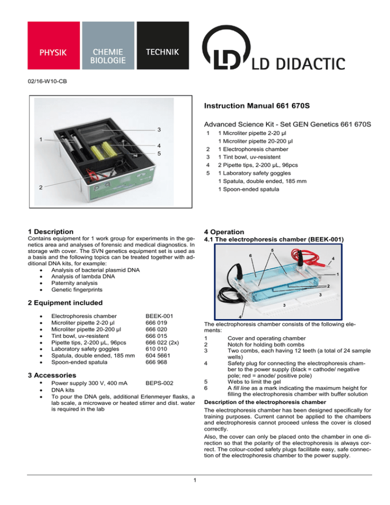
02/16-W10-CB Instruction Manual 661 670S Advanced Science Kit - Set GEN Genetics 661 670S 3 1 1 4 5 2 3 4 5 2 1 Microliter pipette 2-20 μl 1 Microliter pipette 20-200 μl 1 Electrophoresis chamber 1 Tint bowl, uv-resistent 2 Pipette tips, 2-200 μL, 96pcs 1 Laboratory safety goggles 1 Spatula, double ended, 185 mm 1 Spoon-ended spatula 1 Description 4 Operation Contains equipment for 1 work group for experiments in the genetics area and analyses of forensic and medical diagnostics. In storage with cover. The SVN genetics equipment set is used as a basis and the following topics can be treated together with additional DNA kits, for example: Analysis of bacterial plasmid DNA Analysis of lambda DNA Paternity analysis Genetic fingerprints 4.1 The electrophoresis chamber (BEEK-001) 2 Equipment included Electrophoresis chamber Microliter pipette 2-20 μl Microliter pipette 20-200 μl Tint bowl, uv-resistent Pipette tips, 2-200 μL, 96pcs Laboratory safety goggles Spatula, double ended, 185 mm Spoon-ended spatula BEEK-001 666 019 666 020 666 015 666 022 (2x) 610 010 604 5661 666 968 3 Accessories • Power supply 300 V, 400 mA BEPS-002 DNA kits To pour the DNA gels, additional Erlenmeyer flasks, a lab scale, a microwave or heated stirrer and dist. water is required in the lab 1 The electrophoresis chamber consists of the following elements: 1 Cover and operating chamber 2 Notch for holding both combs 3 Two combs, each having 12 teeth (a total of 24 sample wells) 4 Safety plug for connecting the electrophoresis chamber to the power supply (black = cathode/ negative pole; red = anode/ positive pole) 5 Webs to limit the gel 6 A fill line as a mark indicating the maximum height for filling the electrophoresis chamber with buffer solution Description of the electrophoresis chamber The electrophoresis chamber has been designed specifically for training purposes. Current cannot be applied to the chambers and electrophoresis cannot proceed unless the cover is closed correctly. Also, the cover can only be placed onto the chamber in one direction so that the polarity of the electrophoresis is always correct. The colour-coded safety plugs facilitate easy, safe connection of the electrophoresis chamber to the power supply. Instruction manual 661 670S Page 2/3 Description of the power supply Caution: It is essential that the safety plugs be dry when the electrophoresis chamber is connected to the power supply! The devices needed to pour the gel (comb positions and limiting webs) are already integrated into this chamber. This facilitates direct pouring of the gel into the chamber. So there is no need for additional gel pour stations. Since two combs can be used, up to 24 samples can be applied to a single gel. Caution: The temperature of the gel solution should not exceed 55 °C when it is poured into the chamber. Since the electrophoresis chamber has a UV-transparent chamber base, the gel in the chamber can be analysed directly while it sits on the UV table. However, it should be noted that extensive UV radiation can damage the plastic. 4.2 The power supply, 300 V, 400 mA (BEPS-002) The 300 V, 400 mA power supply has been tailored specifically for use in electrophoresis. It is also designed to be used with electrophoresis chambers that have safety sockets. Either one or two electrophoresis chambers can be connected in parallel. The safe and stable current output from the device guarantees reliable test results. Technical data: Output voltage 10 – 300 V Output current 10 – 400 mA Max. power 60 W Output type Constant voltage/constant current Connections Safety sockets for a max. of 2 electrophoresis chambers in parallel Time setting 1 – 999 min with alarm function, continuous Nominal voltage 100 – 240 V~, 50 – 60 Hz, 2 A Putting into operation 1 2 Connect the accompanying power plug. When connecting one electrophoresis chamber: Insert the safety plug of the electrophoresis chamber either into the left or the right pair of safety sockets. Make sure the polarity is correct. When connecting two electrophoresis chambers: Plug the safety plugs of each electrophoresis chamber into either the right or the left pair of safety sockets. Make sure the polarity is correct. Caution: Never use wet plugs with the power supply! The 300 V, 400 mA power supply consists of the following components: 1 Display 2 Voltage parameter selector (volt) with indicator light 3 Current parameter selector (current) with indicator light 4 Time parameter selector (time) with indicator light 5 Safety sockets for connecting up to 2 electrophoresis chambers in parallel 6 Start/ Stop (run/stop) selector with indicator light 7 Reducing the selected parameter (volt, current or time) 8 Increase in the selected parameter (volt, current or time) 9 Reverse side Main "On/Off" switch, main power connection, circuit breaker Please follow the general safety instructions when working with power supplies: 3 4 5 6 The 300 V, 400 mA power supply meets safety specifications for electric measurement, control, regulating and laboratory equipment. It is designed for use in dry spaces suitable for electrical equipment or appliances. Safe operation of the 300 V, 400 mA power supply is ensured when used properly. However, safety is not guaranteed if the equipment is used improperly or carelessly. If safe operation can no longer be assumed, the equipment must be shut down immediately (for example if there is visible damage found). 7 8 Prior to start-up, examine the housing and the control and indication elements for damages. If functional disruptions occur, or if there is visible damage to the equipment, shut it down and secure it against being turned back on unintentionally. Prior to initial start-up, make sure that the value printed on the nameplate (rear of housing) for mains voltage is the same as the local value. 2 Turn on the power supply using the main switch on the back. Activate the time selector to establish a specific duration. The time indicator light will light red. Select the desired time in minutes using the up or down arrow. If the electrophoresis is to be carried out at a constant voltage, first activate the current selector. The current indicator light will light red. Set the current to maximum (400 mA) using the up arrow. Then, set the desired voltage by activating the volt button and using the up and down arrows. If the electrophoresis is to be carried out at constant current, the voltage must first be set to maximum. To do so, press the volt button and set the voltage to 300 V (maximum) using the up arrow. Then, select the current by pressing the current button and enter the desired milliamps using the up and down arrow. Note: If the chamber is being operated at constant current or constant voltage, the other respective parameter must be set to maximum! By pressing the run/stop button, the electrophoresis is started (indicator light with light red). When a time limit is on, the electrophoresis automatically stops after the time has elapsed. By pressing the run/ stop button, the electrophoresis can be stopped manually. Note: If the safety plugs of the electrophoresis chamber/s have been incorrectly connected to the power supply, it cannot be started. A warning tone sounds and the error message "nLd" appears on the display. Page 3/3 4.3 The microliter pipettes 2 – 20 µl and 20 – 200 µl (666 019 and 666 020) Instruction manual 661 670S Caution: The pipettes may only be operated using the right pipette tips. It is imperative you avoid "sucking" the solution to be pipetted into the pipette shaft. Application 1 1 2 3 4 Pipette shaft for holding the pipette tip Pipetting range Volume display Rotating knob for adjusting the desired pipetting volume and push-button for drawing and dispensing the liquid 5 Ejector for removing the pipette tip Description of the microliter pipettes Piston pump microlitre pipettes are very easy to use. The ergonomic shape makes it suitable for both left and right hand operation. The volume dispensed should not be more or less than the range indicated in the volume setting. Select the correct pipette depending on the volume to be pipetted (2 – 20 µl; 20 – 200 µl). 2 Adjust the volume using the rotating knob. 3 Insert the pipette tip onto the pipette shaft. Note: Do not grasp the pipette tips with your hands: risk of contamination! 4 Hold the push-button, place the pipette tip into the liquid and let the push-button raise in a controlled fashion to take the liquid. Note: When taking liquids, always let the push-button release/raise in a controlled fashion so that the liquid taken cannot spray into the shaft of the pipette. 5 To dispense the liquid, slowly press the push-button. Note: Practice in the handling of piston-pump microlitre pipettes is recommended prior to first using them. This can be done very easily, for example by pipetting water. © by LD DIDACTIC GmbH · Leyboldstr. 1 · D-50354 Huerth · Tel: +49-2233-604-0 · Fax: +49-2233-604-222 · E-Mail: info@ld-didactic.de www.ld-didactic.com Technical alterations reserved
