Lighted Pushbutton Switch A3A
advertisement
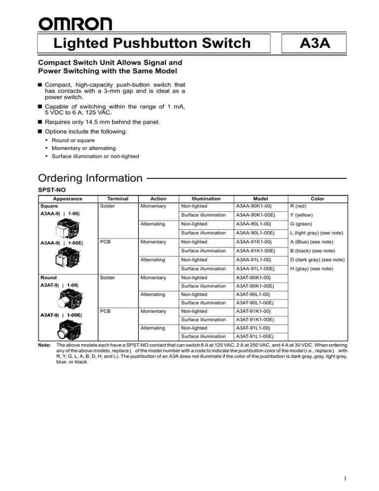
Lighted Pushbutton Switch A3A Compact Switch Unit Allows Signal and Power Switching with the Same Model Compact, high-capacity push-button switch that has contacts with a 3-mm gap and is ideal as a power switch. Capable of switching within the range of 1 mA, 5 VDC to 6 A, 125 VAC. Requires only 14.5 mm behind the panel. Options include the following: ! Round or square ! Momentary or alternating ! Surface illumination or non-lighted Ordering Information SPST-NO Appearance Square Terminal Solder Action Momentary A3AA-9jj1-00j Alternating A3AA-9jj1-00Ej PCB Momentary Alternating Round Solder Momentary A3AT-9jj1-00j Alternating A3AT-9jj1-00Ej PCB Momentary Alternating Note: Illumination Model Color Non-lighted A3AA-90K1-00j R (red) Surface illumination A3AA-90K1-00Ej Y (yellow) Non-lighted A3AA-90L1-00j G (green) Surface illumination A3AA-90L1-00Ej L (light gray) (see note) Non-lighted A3AA-91K1-00j A (Blue) (see note) Surface illumination A3AA-91K1-00Ej B (black) (see note) Non-lighted A3AA-91L1-00j D (dark gray) (see note) Surface illumination A3AA-91L1-00Ej H (gray) (see note) Non-lighted A3AT-90K1-00j Surface illumination A3AT-90K1-00Ej Non-lighted A3AT-90L1-00j Surface illumination A3AT-90L1-00Ej Non-lighted A3AT-91K1-00j Surface illumination A3AT-91K1-00Ej Non-lighted A3AT-91L1-00j Surface illumination A3AT-91L1-00Ej The above models each have a SPST-NO contact that can switch 6 A at 125 VAC, 2 A at 250 VAC, and 4 A at 30 VDC. When ordering any of the above models, replace j of the model number with a code to indicate the pushbutton color of the model (i.e., replace j with R, Y, G, L, A, B, D, H, and L). The pushbutton of an A3A does not illuminate if the color of the pushbutton is dark gray, gray, light gray, blue, or black. 1 A3A A3A SPDT Appearance Terminal Solder Square q A3AA 9jj1 00j A3AA-9jj1-00j Action Momentary Alternating PCB A3AA-9jj1-00Ej Momentary Alternating Solder Round A3AT 9jj1 00j A3AT-9jj1-00j Momentary Alternating PCB A3AT-9jj1-00Ej Momentary Alternating Note: Illumination Model Non-lighted A3AA-90A1-00j Surface illumination A3AA-90A1-00Ej Non-lighted A3AA-90B1-00j Surface illumination A3AA-90B1-00Ej Non-lighted A3AA-91A1-00j Surface illumination A3AA-91A1-00Ej Non-lighted A3AA-91B1-00j Surface illumination A3AA-91B1-00Ej Non-lighted A3AT-90A1-00j Surface illumination A3AT-90A1-00Ej Non-lighted A3AT-90B1-00j Surface illumination A3AT-90B1-00Ej Non-lighted A3AT-91A1-00j Surface illumination A3AT-91A1-00Ej Non-lighted A3AT-91B1-00j Surface illumination A3AT-91B1-00Ej Color R (red) Y (yellow) G (green) L (light gray) (see note) A (blue) (see note) B (black) ( ) (see ( note)) D (dark (d k gray)) (see ( note) t ) H (gray) (see note) The above models each have a SPDT contact that can switch 3 A at 125 VAC and 2 A at 30 VDC. When ordering any of the above models, replace j of the model number with a code to indicate the pushbutton color of the model (i.e., replace j with R, Y, G, L, A, B, D, H, and L). The pushbutton of an A3A does not illuminate if the color of the pushbutton is dark gray, gray, light gray, blue, or black. Model Number Legend A3Aj-9jj1-jj 1 1. 2 3 4 5 Shape A: Square T: Round 2. Terminal 0: Solder 1: PCB 3. Switch 6 A at 125 VAC, 2 A at 250 VAC, 4 A at 30 VDC A: Momentary (SPDT) B: Alternating (SPDT) K: Momentary (SPST-NO) L: Alternating (SPST-NO) 4. 2 Illumination 00: Non-lighted 00E: Surface illumination 5. Color Switch (Non-lighted Models) L: Light gray R: Red Y: Yellow G: Green A: Blue B: Black D: Dark gray H: Gray LED (Surface Illumination Models) R: Red Y: Yellow G: Green A3A A3A Accessories (Order Separately) Flange Select according to panel color. Name Shape Classification Square, 12.7 x 12.7 Flange Flange alone Round, 12.7 dia. Model Black A3A-241 Light gray A3A-242 Black A3A-251 Light gray A3A-252 Leaf spring Square, 12.7 x 12.7 Flange and leaf spring (one each) Round, 12.7 dia. Note: A3A-200 Black A3A-211 Light gray A3A-212 Black A3A-221 Light gray A3A-222 An A3A with solder terminals is provided with a round or square black flange and flat spring for the switching mechanism of the A3A. A round black flange is provided with each A3A having solder terminals and a round pushbutton. A square black flange is provided with each A3A having solder terminals and a square pushbutton. Specifications Contact Ratings Type Contact form SPST-NO High capacity Note: Resistive load 6 A at 125 VAC 2 A at 250 VAC 4 A at 30 VDC Minimum allowable load: 5 VDC 1 mA (Resistive) LED Ratings Item Surface illumination Red Standard value 2.1 V Maximum value 2.8 V Standard value 15 mA Maximum value 25 mA Permissible loss PD Absolute max. value 70 mW Reverse voltage VR Absolute max. value 3V Forward voltage VF Forward current IF Note: Yellow (2.2 V) Green 2.2 V The above built-in LEDs do not have a resistor. Connect to each of the above built-in LEDs a resistor that satisfies the above conditions. 3 A3A A3A Characteristics Mechanical: Momentary action: Alternating action: Operating frequency 120 operations/min max. 60 operations/min max. (see note 1) Electrical: 20 operations/min max. Insulation resistance 100 M" min. (at 500 VDC) Contact resistance 100 m" max. (initial value) for high-capacity Dielectric strength 600 VAC, 50/60 Hz for 1 min between terminals of same polarity 2,000 VAC, 50/60 Hz for 1 min between terminals of different polarity 2,000 VAC, 50/60 Hz for 1 min between each terminal and ground 600 VAC, 50/60 Hz for 1 min between LED terminal (see note 2) Vibration resistance Malfunction: 10 to 55 Hz, 1.5-mm double amplitude Shock resistance Destruction: 500 m/s2 (approx. 50G) Malfunction: 150 m/s2 (approx. 15G) Life expectancy Mechanical: Momentary action: Alternating action: 1,000,000 operations min. 50,000 operations min. Electrical: 50,000 operations min. Ambient temperature Operating: --10#C to 55#C (with no icing) Storage: --25#C to 65#C Ambient humidity Operating: 35% to 85% Weight Approx. 3.2 g Note: 1. A setting and resetting is regarded as one operation. 2. A dielectric strength of 600 VAC at 50 or 60 Hz for one minute is ensured for the A3A without a built-in LED. 3. An A3A alternating-operation model and an A3A with standard ratings have an electrical life of 100,000 times minimum. An A3A with a 10-mA resistive load at 6 VDC has an electrical life of 1,000,000 times. Approved Standards UL (File No. E41515)/CSA (File No. LR45258) 6 A at 125 VAC, 2 A at 250 VAC, 4 A at 30 VDC Operating Characteristics OF max. 250 gf (2.45 N) RF min. 15 gf (0.15 N) TT Approx. 2 mm PT max. 1.5 mm 0.5 mm LTA min. (see note) Note: The above lock stroke figure applies to the A3A Alternating Operation model only. Contact form Type Resistive load High capacity SPST-NO 6 A at 125 VAC 2 A at 250 VAC 4A at 30 VDC General purpose SPDT 3 A at 125 VAC 2 A at 30 VAC 4 A3A A3A Nomenclature Pushbutton Unit Pushbutton Square (A3AA) Illumination Round (A3AT) Diffusion sheet (milky white) Color Non-lighted Model Red, yellow, light gray, gray, dark gray, green blue, black Surface Illumination Model Flange Red, yellow, green Leaf spring Switch Unit Ratings (Standard load) 6 A at 125 VAC 2 A at 250 VAC 4 A at 30 VDC Minimum applicable load: 1 mA at 5 VDC (resistive load) Terminals Solder terminal PCB terminal Contact Type Contact form Type Double-break type Contact type SPST-NO NO Double-throw type NO SPDT NC COM Note: NO 1. The above is for the A3AA. 2. An A3A with solder terminals is provided with a black flange and flat spring for the switching mechanism, however an A3A with PCB terminals is not provided with them. If a black flange and flat spring are required for an A3A with PCB terminals, order them from your OMRON representative. 5 A3A A3A Dimensions Note: 1. All units are in millimeters unless otherwise indicated. 2. The illustrations below show switches with solder terminals, without a flange or leaf spring. Non-lighted Model Square Pushbutton SPDT SPST-NO Square push-button 8.9 $ 8.9 Round Pushbutton Round push-button Three, t0.4 terminals Two, t0.4 terminals 8.9 dia. Surface Illumination Model Square Pushbutton SPST-NO SPDT Square push-button 8.9 $ 8.9 Surface illumination Round Pushbutton Round push-button Three, t0.4 terminals Two, t0.4 terminals 8.9 dia. Surface illumination Two, t0.3 LED terminals Two, t0.3 LED terminals Accessories (Order Separately) Note: Unless otherwise specified, a tolerance of %0.4 mm applies to all dimensions. A3A-200 Leaf Spring A3A-24j Flange (Square) A3A-25j Flange (Round) 12.7 dia. 9.1 dia. 12.7 $ 12.7 9.1 $ 9.1 t = 0.3 6 1.0 1.0 A3A A3A Panel Cutouts Square Pushbutton 11.5 +0.2 0 Flange Panel (see note) 11.5 +0.2 0 Leaf spring 14.5 max. Round Pushbutton 11.5 +0.2 0 Note: dia. Recommended panel thickness: 1 to 1.6 mm For Side-by-side Mounting Mounting Horizontal multiple mounting Square pushbutton 15.3 min. Round pushbutton 11.5 +0.2 0 dia. 15.3 min. 3.8 min Vertical multiple mounting 11.5 +0.2 0 dia. 12.7 min. 7 A3A A3A Terminals Solder terminal SPSTNO PCB terminal Non-lighted Models Non-lighted Models Terminals Lighted Models t0.3 terminal t0.4 terminal Lighted Models Terminal Arrangement (Bottom View) 0.8 0.8 x 2 Terminal Arrangement (Bottom View) LED terminal LED terminal PCB Dimensions (Bottom View) Holes for models with illuminating push-button Terminal for models with an illuminating push-button Terminal for models with an illuminating push-button 10.16 4.48 Four, 1 dia. holes SPDT Non-lighted Models Switch terminal: t0.4 Switch terminal: t0.4 Lamp terminal: t0.3 Lighted Models Non-lighted Models LED terminal LED terminal 8 Switch terminal: t0.4 LED terminal: t0.3 Switch terminal: t0.4 Terminal Arrangement (Bottom View) Terminal Arrangement (Bottom View) Lighted Models PCB Dimensions (Bottom View) Five, 1-dia. holes Holes for models with illuminating push-button A3A A3A Installation Mounting Switch Unit on a Panel Mount Leaf Spring Press the leaf spring into the fitted groove on the upper surface of the switch unit. For an easier fitting, first fit one side of the leaf spring, then press the other side into the fitting groove. Removing Switch Unit Insert a small flat-bladed screwdriver or tweezers into the flange support exposed on the rear of the panel. Pry up on each side to pull out the switch unit. Panel Flat-bladed screwdriver or tweezers Leaf spring Leaf spring fitting groove Switch unit Note: Be sure to fit the leaf spring exactly into the groove, and do not allow it to slip out of the groove. Note: Do not pry up the flange support more than necessary or the switch holding portions may be damaged. Mount Flange on Panel Insert the flange from the front surface of the panel. Flange Panel Guide The flange has two opposing guides to facilitate its insertion into the panel cutout hole. Be sure the flange does not remain tilted with respect to the panel surface after being installed. Cross Section Flange Panel (t = 1 to 1.6 mm) Note: The mounting direction of the flange determines the orientation of the switch unit. Fit Flange with Switch Unit While holding the flange, insert the opposing supports into the gaps between the leaf spring and switch unit on the longer sides of the housing, and fit the rectangular hole of the flange with the projections of the switch housing. Support Panel Projection Note: Completely remove any burrs on the panel cutout surface; otherwise, the flange and switch unit will not attach solidly. 9 A3A A3A Precautions Operation When operating an A3A, make sure that the A3A has a pushbutton. Do not operate the A3A with a screwdriver or tweezers without mounting a pushbutton to the A3A, otherwise the A3A may malfunction. LED Characteristics (VF -- IF Characteristics) Ta: Ambient Temperature Red I F (mA) Mounting When opening a hole on a panel to mount an A3A to the panel, make sure that the hole has no burr. When mounting a flange to the switching mechanism of an A3A, make sure that the flange and the casing of the switching mechanism are engaged securely. Ta = 50#C Ta = 25#C Ta = 0#C Wiring VF (V) Green I F (mA) Ta = 50#C Ta = 25#C Ta = 0#C VF (V) Yellow I F (mA) When soldering the terminals of an A3A, refer to the following. 1. For manual soldering: Use a soldering iron with an input of 30 W to solder the terminals at a temperature of 280#C maximum within five seconds. 2. For automatic soldering: Solder the terminals at a temperature of 240#C within three seconds. Do not impose any external force on the terminals for one minute after the terminals are soldered. Do not solder the terminals at a temperature of 300#C or more, otherwise the resin casing of the A3A will deform and the location of the terminals will change. Do not pull the terminals of any A3A with a force exceeding 0.6 kgf (5.34 N), otherwise the joint part of the A3A may be damaged. When soldering the terminals of an A3A, apply non-corrosive rosin flux to the terminals. After soldering the terminals of an A3A, do not wash the A3A with any solvent. When mounting an A3A to a PCB and soldering the terminals of the A3A to the PCB, make sure that the flux will not rise above the surface of the PCB. Operating Environment When using an A3A, make sure that dust, metal powder, or oil will not penetrate into the interior of the A3A. Ta = 50#C Ta = 25#C Ta = 0#C LED The back of an A3A with an LED indicates the polarity of the LED. Wire the LED correctly according to the polarity. An A3A with a built-in LED does not have a limiting resistor. Connect a limiting resistor to the build-in LED. The resistance can be calculated by using the following expression. R = (E --VF)/IF (") E: Applied voltage (V) VF: LED forward voltage (V) IF: LED forward current (A) Note: Make sure that the limiting resistor connected to the built-in LED of an A3A satisfies the characteristics of the built-in LED. The mean forward current of the built-in LED must be 8 mA minimum. Example Conditions: Red LED with an IF of --10 mA at 24 V and a Ta of 25#C. From the red LED characteristic below, VF will be 2 V when IF is 10 mA. Therefore, R = (24 V -- 2 V)/0.01 A = 2,200 ". Thus the recommended resistance is 2.2 k" at 0.5 W (2 x IF2R). The permissible wattage of the resistor must be twice as large as the required wattage. VF (V) Pushbutton When exchanging the pushbutton unit (except the ones for the mechanical indicator models) with a new one, pull out the pushbutton unit from the switch unit, holding the pushbutton unit in the longitudinal direction. Do not remove the pushbutton unit of the mechanical indicator model. Engraving of Pushbutton Depth of engraving: 0.3 mm max. for illuminating pushbutton 0.5 mm max. for non-illuminating pushbutton Since the pushbutton unit is made of polycarbonate, use an alcoholbased solvent when cleaning the unit. Pressing of Pushbutton Apply firm pressure to the pushbutton unit when operating it. In doing so, however, do not apply a pressure greater than 1.2 kgf (11.8 N). ALL DIMENSIONS SHOWN ARE IN MILLIMETERS. To convert millimeters into inches, multiply by 0.03937. To convert grams into ounces, multiply by 0.03527. Cat. No. A025-E1-4 10
