ATI-DM335 - AT Monitors
advertisement

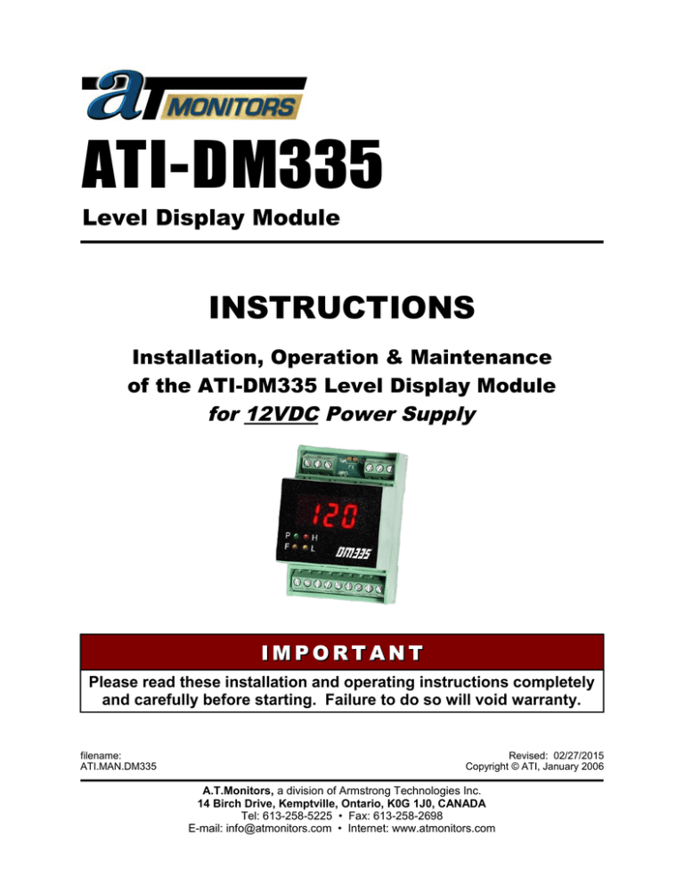
ATI-DM335 Level Display Module INSTRUCTIONS Installation, Operation & Maintenance of the ATI-DM335 Level Display Module for 12VDC Power Supply IMPORTANT Please read these installation and operating instructions completely and carefully before starting. Failure to do so will void warranty. filename: ATI.MAN.DM335 Revised: 02/27/2015 Copyright © ATI, January 2006 A.T.Monitors, a division of Armstrong Technologies Inc. 14 Birch Drive, Kemptville, Ontario, K0G 1J0, CANADA Tel: 613-258-5225 • Fax: 613-258-2698 E-mail: info@atmonitors.com • Internet: www.atmonitors.com TABLE OF CONTENTS Section Title Page 1 - WARRANTY ......................................................................................................................... 1 1.1 - LIABILITY ....................................................................................................................... 1 1.2 - MODIFICATIONS AND SUBSTITUTIONS .....................................................................1 1.3 - PRODUCT RETURN ......................................................................................................1 2 - PRODUCT INFORMATION ..................................................................................................2 2.1 - DISPLAY MODULE.........................................................................................................2 2.2 - FACTORY SETTINGS....................................................................................................2 3 - PRODUCT DESCRIPTION....................................................................................................3 3.1 - GENERAL DESCRIPTION..............................................................................................3 4 - INSTALLATION.................................................................................................................... 5 4.1 - LOCATION AND MOUNTING.........................................................................................5 4.2 - WIRING OF THE SYSTEM.............................................................................................6 4.2.1 - SHIELDING AND GROUND.....................................................................................6 5 - OPERATION AND CALIBRATION.......................................................................................7 5.1 - OPERATION................................................................................................................... 7 5.2 - CALIBRATION................................................................................................................7 6 - PREVENTIVE MAINTENANCE.............................................................................................8 6.1 - GENERAL....................................................................................................................... 8 6.2 - VERIFICATION OF OPERATION...................................................................................8 ATI-DM335, Level Display Module 1 - WARRANTY The ATI-DM335 Level Display Module is warranted against defects in material and workmanship for a period of one (1) year from date of shipment. During the warranty period, Armstrong Technologies Inc. (ATI) will repair or replace components that prove to be defective in the opinion of ATI. ATI is not liable for auxiliary interfaced equipment, or consequential damage. This warranty shall not apply to any product, which has been modified in any way, which has been repaired by any other party other than a qualified technician or authorized ATI representative, or when such failure is due to misuse or conditions of use. 1.1 - LIABILITY All ATI products must be installed and maintained according to instructions. Only qualified technicians should install and maintain the equipment. ATI shall have no liability arising from auxiliary interfaced equipment, for consequential damage, or the installation and operation of this equipment. ATI shall have no liability for labour or freight costs, or any other costs or charges in excess of the amount of the invoice for the products. THIS WARRANTY IS IN LIEU OF ALL OTHER WARRANTIES, EXPRESSED OR IMPLIED, AND SPECIFICALLY THE WARRANTIES OF MERCHANTABILITY AND FITNESS FOR A PARTICULAR PURPOSE. THERE ARE NO WARRANTIES THAT EXTEND BEYOND THE DESCRIPTION ON THE FACE THEREOF. 1.2 - MODIFICATIONS AND SUBSTITUTIONS Due to an ongoing development program, ATI reserves the right to substitute components and change specifications at any time without incurring any obligations. 1.3 - PRODUCT RETURN All products returned for warranty service will be by prepaid freight and they will only be accepted with an R.G.A. number issued by ATI. All products returned to the client will be freight collect. WARNING USING ELECTRICALLY OPERATED EQUIPMENT NEAR GASOLINE OR OTHER COMBUSTIBLE VAPOURS MAY RESULT IN FIRE OR EXPLOSION, CAUSING PERSONAL INJURY AND PROPERTY DAMAGE. CHECK TO ASSURE THE WORKING AREA IS FREE FROM SUCH HAZARDS DURING INSTALLATION OR WHEN PERFORMING MAINTENANCE, AND USE PROPER PRECAUTIONS. 1 ATI-DM335, Level Display Module 2 - PRODUCT INFORMATION NOTE: This page must be filled-in at site by client, contractor or installer and this manual returned to the owner or manager. 2.1 - DISPLAY MODULE Module Serial Number ……………………………..... Power Supply Requirement ……………………….... 12 VDC Power Supply Current (minimum) ………………..... 200mA Operating Temperature * ....………………………... 0 to +50 °C (+32 to +122 °F) Relative Humidity …………………………………..... 0 to 95 %, non-condensing Display Type ………………………………………..... 3-1/2 digit LED display, 0.37" high Alarm Indicators ………..…………………………..... LEDs for Fail, Low alarm & High alarm Input …………………………………………………... 4 to 20 mA DC Output (optional) ………..………………………….... 4 to 20 mA DC Relays (Fail, Low, High) ……………….................... 0.3A @ 110VDC/125VAC, 1A @ 30VDC 2.2 - FACTORY SETTINGS DISPLAY: 4 mA ……………………………………………………... 20 mA ………………………………………………….... Low Alarm Trip Point ……………………..................... High Alarm Trip Point ………................…………….... RELAYS: Relay Coils Low Alarm ………… Normally Non-Energized High Alarm ……….. Normally Non-Energized Fail Alarm ………... Normally Energized Note: All Armstrong Technologies Inc. products must be installed and maintained according to instructions, to ensure proper operation. Only qualified technicians should install and maintain the equipment. 2 ATI-DM335, Level Display Module 3 - PRODUCT DESCRIPTION 3.1 - GENERAL DESCRIPTION The ATI-DM335 Level Display Module is designed to accept a 4-20 mA signal from a variety of sensors or transmitters and offers local or remote liquid level readout, alarm indication and contacts. It features a 3,1/2 digit LED display for indicating liquid levels and has relay outputs for fail, low and high alarms. A 4-20 mA repeater output is available which matches the input signal. As a DIN rail mounted unit, this module can be combined with a wide assortment of monitoring instruments for local indication and alarm functions. 1) DISPLAY: 3-1/2 digit display for liquid level indication. 2) LED INDICATORS: LED indicators for power, fail, low and high alarm. 3) SENSOR/TRX TERMINALS: For sensor connection to module. 4) POWER/MONITOR TERMINALS: For connection to power supply or host monitor. NOTE: Use 250R resistor for 1-5V output (see Figure 2). 5) RELAY TERMINALS: For connecting auxiliary equipment to the relay contacts. FIGURE 1: Typical DM335 level display module wiring (front view). 3 ATI-DM335, Level Display Module FIGURE 2: DM335 level display module wiring (front view) with signal output. 4 ATI-DM335, Level Display Module 4 - INSTALLATION 4.1 - LOCATION AND MOUNTING Care should be taken to securely fasten the DM335 liquid level display module on a solid, nonvibrating surface or structure at eye level. Mount the monitor in an area where the unit can be observed periodically. The mounting holes are located behind the cover screws. The module can be supplied in an IP54 rated enclosure with clear windowed cover (as shown in FIGURE 2), in an explosion-proof housing, or can be simply snapped onto a DIN rail in an existing enclosure. To remove the module, a small flat screwdriver is required. Insert the tip of the screwdriver into the slot of the release tab, below the relay terminal blocks. Then, push the handle of the screwdriver towards the display and tilt the module in the same direction. This will pop the module off of the DIN rail. FIGURE 3: Example of mounting the housing with level display module. 5 ATI-DM335, Level Display Module 4.2 - WIRING OF THE SYSTEM Display Module: Connection to the host monitor/power supply is made at the MONITOR CONNECTION terminal block (refer to FIGURE 1 and 2). All connections should be made using shielded 2 or 3 conductor cable, depending if signal output wire is required. Sensor: Each liquid sensor connects to the Sensor terminal block's "–,S,+" (refer to FIGURE 1). All connections should be made with shielded 2-conductor cable. CAUTION: The black "S" lead from the sensor must NEVER be connected to ground. This could cause erratic readings or possibly damage the sensor. Relays: Three SPDT relays within the module are available, which change state with fail, low and high alarm causing contact transfer. Auxiliary control devices may be connected to these contacts providing they do not exceed relay ratings. See section 2.2 FACTORY SETTINGS for relay set-up. Refer to FIGURE 1 for relay contact arrangement. NOTE: For Class I locations, use appropriate conduit sealing fittings. 4.2.1 - SHIELDING AND GROUND To obtain efficient shielding against EMI and RFI, the use of metal conduit from the sensor housing to the DM335 module enclosure is highly recommended. Install a grounding bushing (as shown at left) on the conduit at the module enclosure and connect a lead from earth ground to the ground lug on the bushing. If shielded cable is also used, connect the braided shield of the cable to the same ground lug. 6 ATI-DM335, Level Display Module 5 - OPERATION AND CALIBRATION 5.1 - OPERATION When power is applied, the green power LED will light and the display will register a value representing the level of liquid. If a fail condition occurs on the connected sensor the fail LED will activate and the fail relay will change state. If the liquid level drops to the sensor’s low alarm trip point setting the yellow LED will activate and the low alarm relay will change state. If the liquid level rises to the sensor’s high alarm trip point setting the red LED and high alarm relay will activate or deactivate depending on specified set-up. The display on the module reflects the level of liquid seen by the connected sensor. The signal current input from the sensor is repeated and fed to the module's output terminals ). A monitoring device with a maximum impedance of 250 ohms may be connected to this output circuit. If an analog output is not required, short the "S" terminal to the "–" terminal. 5.2 - CALIBRATION The DM335 level display module is factory calibrated based on customer requests and/or standards. Calibration should last for the life of the module. Recalibration is only necessary when changing the level trip points. See section 2.2 for FACTORY SETTINGS. 7 ATI-DM335, Level Display Module 6 - PREVENTIVE MAINTENANCE 6.1 - CLEANING CAUTION: Avoid hose spraying and other conditions that could allow liquid to enter the enclosure and cause possible damage to the internal components. Do NOT use any abrasive products. Do NOT use cleaners that contain ammonia. The monitor enclosure should be wiped clean regularly, only with a soft cloth and a solution of water with mild soap or detergent. Rinse well with clear water, then blot dry using a clean soft chamois or blow any remaining water off using a can of compressed air. To help protect the plastic enclosure, a thin coat of floor or automobile wax can be evenly applied using a clean soft cloth, then buff lightly and wipe with a clean, damp cloth to remove static electricity. To remove foreign material (caulking, grease, fresh paint, etc.) use naphtha or isopropyl alcohol, then clean as described above. NOTE: The enclosure's IP54 rating will protect the monitor from normal conditions such as cleaning, dust, rain, and light splashing from vehicles. 6.2 - VERIFICATION OF OPERATION To verify the operation of the system, make sure that each sensor and/or transmitter is still responding to liquid level changes and that the correct condition is shown on the display. This test should be performed every 2 months, but for more demanding applications, verification should be performed on a weekly basis. 8

