Phy 3311 Electronics Lab 3: DC Circuits Finale, and introducing
advertisement

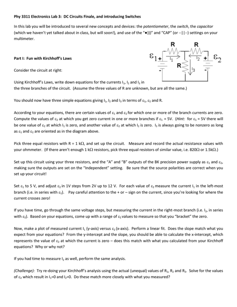
Phy 3311 Electronics Lab 3: DC Circuits Finale, and introducing Switches In this lab you will be introduced to several new concepts and devices: the potentiometer, the switch, the capacitor (which we haven’t yet talked about in class, but will soon!), and use of the “●)))” and “CAP” (or ||) settings on your multimeter. Part I: Fun with Kirchhoff’s Laws Consider the circuit at right: Using Kirchhoff’s Laws, write down equations for the currents I1, I2 and I3 in the three branches of the circuit. (Assume the three values of R are unknown, but are all the same.) You should now have three simple equations giving I1, I2 and I3 in terms of 1, 2 and R. According to your equations, there are certain values of 1 and 2 for which one or more of the branch currents are zero. Compute the values of 2 at which you get zero current in one or more branches if 1 = 5V. (Hint: for 1 = 5V there will be one value of 2 at which I1 is zero, and another value of 2 at which I2 is zero. I3 is always going to be nonzero as long as 1 and 2 are oriented as in the diagram above. Pick three equal resistors with R = 1 k, and set up the circuit. Measure and record the actual resistance values with your ohmmeter. (If there aren’t enough 1 k resistors, pick three equal resistors of similar value, i.e. 820 or 1.5k.) Set up this circuit using your three resistors, and the “A” and “B” outputs of the BK precision power supply as 1 and 2, making sure the outputs are set on the “Independent” setting. Be sure that the source polarities are correct when you set up your circuit! Set 1 to 5 V, and adjust 2 in 1V steps from 2V up to 12 V. For each value of 2 measure the current I1 in the left-most branch (i.e. in series with 1). Pay careful attention to the + or – sign on the current, since you’re looking for where the current crosses zero! If you have time, go through the same voltage steps, but measuring the current in the right-most branch (i.e. I2, in series with 2). Based on your equations, come up with a range of 2 values to measure so that you “bracket” the zero. Now, make a plot of measured current I1 (y-axis) versus 2 (x-axis). Perform a linear fit. Does the slope match what you expect from your equations? From the y-intercept and the slope, you should be able to calculate the x-intercept, which represents the value of 2 at which the current is zero – does this match with what you calculated from your Kirchhoff equations? Why or why not? If you had time to measure I2 as well, perform the same analysis. (Challenge): Try re-doing your Kirchhoff’s analysis using the actual (unequal) values of R1, R2 and R3. Solve for the values of 2 which result in I1=0 and I2=0. Do these match more closely with what you measured? Part II: The Wheatstone Bridge Consider the circuit shown at right. R1 is a variable resistor; use one of the blue 1 k potentiometers (variable resistors) on the electronics table. A potentiometer has three terminals: the resistance between the “far” terminals is the full 1 k (like a regular 1 k resistor), while the resistance between either end and the center terminal is a variable amount that is controlled by turning the knob on the end (use a screwdriver for this purpose); the sum of the two “inside” resistances is the full 1 k. The total range of 1 k is covered in 15 turns of the knob, which slides the center contact along the length of the 1k resistor inside. So R1 in this circuit is represented by two of the three connections on the potentiometer: the middle one and either of the end terminals (your choice). Quickly verify the potentiometer’s behavior by installing it on your breadboard and measuring the resistances between the pairs of terminals as you turn of the knob. (Don’t spend too much time on this; just satisfy yourself that the potentiometer works, and that you understand its operation.) Note down some of your qualitative observations. R3 is an “unknown” resistor (actually, it is an ordinary resistor whose color bands have been covered by black tape. No peeking!). Your goal is to use this circuit to determine the value of R3. You can show that the voltage across, and thus the current through, the ammeter will be zero when: R3/R1 = R4/R2 Set up the circuit on your breadboard, using the 1 k pot for R1, the “unknown resistor” for R3, R2 = 1 k, R4 = 4.7 k, and = 10 V. Adjust the knob on the potentiometer until the current through the ammeter goes to zero. You will want to move quickly at first, using “feedback” from the ammeter (play “hot / cold”) to figure out which way to turn the knob. Then move more slowly to accurately “zero out” the ammeter reading. (You may want to switch to the Extech meter in “mA” setting to accurately find the zero!) When the ammeter is zeroed out to your satisfaction, remove the potentiometer from the circuit and measure the resistance between the two terminals you were using to represent R1. From this value of R1, compute the value of the unknown resistance R3. Now, remove R3 from the circuit and directly measure its resistance with your ohmmeter. How close are your two values for R1? Did you do as well as you think you can? Or do you think you can do better? Finally, remove the black tape from R3, and see whether the “nominal” resistance value from the color bands matches with your expectation from the measurements. Of these three values of R (the nominal value from the bands, the measured ohmmeter value, and the value from your analysis of the Wheatstone bridge), which do you think is the most accurate? Part III: Introducing the switch I will bring several types of switches (SPST, SPDT, DPST, DPDT) to the lab, which can be identified by the numbers of terminals they have, and the operation of the switch lever. Please read over the handout on switches for more information about switch types and operation. Play around for a while to become familiar with their operation. Try several types. Connect your meter to different pairs of terminals, and see what happens as you throw the lever. (It may help to use alligator or hook leads to do this!) For this purpose, it is most efficient to use the “●)))” setting on the multimeter. In this setting, the meter operates as an ohmmeter, but also beeps when a low resistance (a “short”) exists between the leads. (Try it by touching the leads together!) This enables you to quickly determine which terminals are connected, and which are not, simply by touching the leads to the terminals and listening. This is extremely useful when troubleshooting a malfunctioning device! You don’t need to spend too much time on this, only enough to satisfy yourself that you understand how these switches work, and to correctly identify what type of switch (e.g. SPST, DPDT) a given switch is. Note: If there aren’t enough switches with attached leads, you might have to solder some wires on. Soldering, yay! Part IV: Introducing the capacitor (Note: we haven’t yet talked about the capacitor in the course. But we will soon, and you should remember a little about capacitors from physics last spring…) Select a few capacitors with C = 0.01 F to C = 1 F from the bin (no color code, just read the numbers right off). First, as is always good practice when starting work with a capacitor, short the two leads against each other to discharge any charge that may have accumulated. Using your multimeter set to the setting, attempt to measure the resistance of one of your capacitors. (Think about how to hold the leads to the capacitor’s terminals – if you hold them in your hands, you will place your own resistance R ~ 200 k in parallel with the capacitor!) Once the value stabilizes, what is it? What you would expect to see, given what you know about capacitors and the operation of the ohmmeter? After this, set your meter to “V” (DC) and measure the voltage between the capacitor terminals. What do you see? Try the other capacitors as well. (If you wish to repeat the measurement, short out the capacitor leads for a few seconds to completely discharge it.) Now, using a meter set to the “CAP” (or ||) setting, measure the same capacitors. What values do you get? How do they compare to the nominal value? (I will leave aside the question of how the “CAP” setting works until we talk about AC circuits. It turns out that the “CAP” setting works very similarly to the ohmmeter, although it applies an AC voltage rather than a DC voltage, and measures something known as “capacitive reactance.” For now, we’ll just marvel at the fact that it works.)


