General Specifications
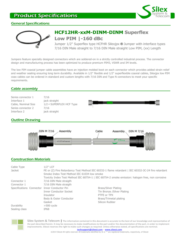
HCF12HR-xxM-DINM-DINM Superflex
Low PIM |-160 dBc
Jumper 1/2" Superflex type HCFHR Silexjpx ® Jumper with interface types
7/16 DIN Male straight to 7/16 DIN Male straight Low PIM, (xx) Length
Jumpers feature specially designed connectors which are soldered-on in a strictly controlled industrial process. The connector
design and manufacturing process has been optimized to produce premium PIM3, VSWR and IM levels.
The low PIM coaxial jumper cable assemblies have an injection molded boot on each connector which provides added strain relief
and weather sealing ensuring long term durability. Available in 1/2" flexible and 1/2" superflexible coaxial cables, Silexjpx low PIM
coax cables can be ordered in standard and custom lengths with 7/16 DIN and Type N connectors to meet your specific
requirements.
Cable assembly
Series connector 1
Interface 1
Cable, Nominal Size
Series connector 2
Interface 2
7/16
jack straight
1/2〃SUPERFLEX HCF Type
7/16
jack straight
Outline Drawing
Construction Materials
Cable Type
Jacket
1/2" LCF
PE or (Z) Fire Retardancy Test Method IEC 60332-1 flame retardant | IEC 60332-3C-24 fire retardant
Smoke Index Test Method IEC 61034 low smoke
Toxicity Index Test Method IEC 60754-1 | IEC 60754-2 smoke emission: halogen free, non corrosive
Connector 1
7/16 DIN Male straigth
Connector 1
7/16 DIN Male straigth
Specifications Connector Inner Conductor Pin
Brass/Silver Plating
Inner Conductor Socket
Tin Bronze /Silver Plating
Insulator
PTFE or TPX
Body & Outer Conductor
Brass/Trimetal plating
Gasket
Silicon Rubber
Durability
>500 cycle
Sealing class
IP68
Silex System & Telecom | The information contained in this document is accurate to the best of our knowledge and representative of
the part described herein. It may be necessary to make modifications to the part and/or the documentation of the part, in order to implement
improvements. Silexst reserves the right to make such changes as required. Unless otherwise stated, all specifications are nominal.
techsupport@silexst.com – www.silexst.com
©2014 Silexst All rights reserved. All trademarks identified by ® or ™ are registered trademarks, respectively, of Silexst
Electrical Specifications
Frequency Range
Impedance Ohms
Maximum VSWR
Velocity Propagation
RFShielding
PeakPower
Passive Intermodulation
DC to 2.7 GHz
50 Ω
1.11:1
83%
120 dB
16 KWatts
-160 dBc
VSWR (Return Loss, dB)
1.065 (30) @ 1710 - 1990 MHz
1.065 (30) @ 2000 - 2200 MHz
1.083 (28) @ 2200 - 2700 MHz
Environmental Specifications
Installation Temperature, °C(°F) -25 to 60 (-13 to 140 )
Operation Temperature, °C(°F) -50 to 85 (-58 to 185 )
Storage Temperature, °C(°F) -70 to 85 (-94 to 185 )
Jumper Assembly Sample
Example Order Number: LCF12STD4M DINMA DINM
Cable
Types
Length in
Inches
LCF12STD
HCF12STD
M
M
LMR240
LMR300
LMR400
RG8
RG59
RG213
RG214
M
M
M
M
M
M
M
Connector 1
-
Type Connector
DIN Male
DIN Female
DIN Male Right
Angle
N Male
N Female
N Male Right Angle
Connector 2
=
LCF12STD
4M
DINMA
DINM
DINM
DINF
DINMA
NM
NF
NMA
Connector 1:DIN Male Right Angle
Connector 1: DIN Male 7/16
Length: 4 metres
Cable Type: LCF12STD
Regulatory Compliance/Certifications
RoHS 2011/65/EU RoHS Compliant
Designed, manufactured and/or distributed under quality management system
All specifications are subject to change. See www.silexst.com for the most current information. Revised: September 09, 2014
Silex System & Telecom | The information contained in this document is accurate to the best of our knowledge and representative of
the part described herein. It may be necessary to make modifications to the part and/or the documentation of the part, in order to implement
improvements. Silexst reserves the right to make such changes as required. Unless otherwise stated, all specifications are nominal.
techsupport@silexst.com – www.silexst.com
©2014 Silexst All rights reserved. All trademarks identified by ® or ™ are registered trademarks, respectively, of Silexst

