Lab #3 Series Resistors

BME 3511 Laboratory 3
Resistors in Series
Objective:
The objective of this exercise is to understand how to connect resistors in series and to use the NI myDAQ to measure resistance and voltage. Upon the completion of this lab, the student will:
Connect resistors in series.
Measure individual resistance as well as equivalent resistance.
Measure voltage across a series circuit.
Background:
When resistors are connected in series, then they have the following properties:
The current at all points of the circuit is equivalent since there is only one path for the current to travel.
The equivalent resistance of a series circuit is obtained by adding all the resistances. Here is a generic formula for the equivalent resistance across a circuit:
R eq
= R
1
+ R
2
+ R
3
+ ...
The voltage in a series circuit varies across each resistive component and can be calculated using ohms law:
Total Voltage: V=I*R eq
Voltage across resistor n: V=I*R n
Now we will do an example of how to measure these values using the NI myDAQ. The first step is to open the DMM on the computer (this tutorial is a general guideline, therefore your computer layout might be different by the general idea is the same):
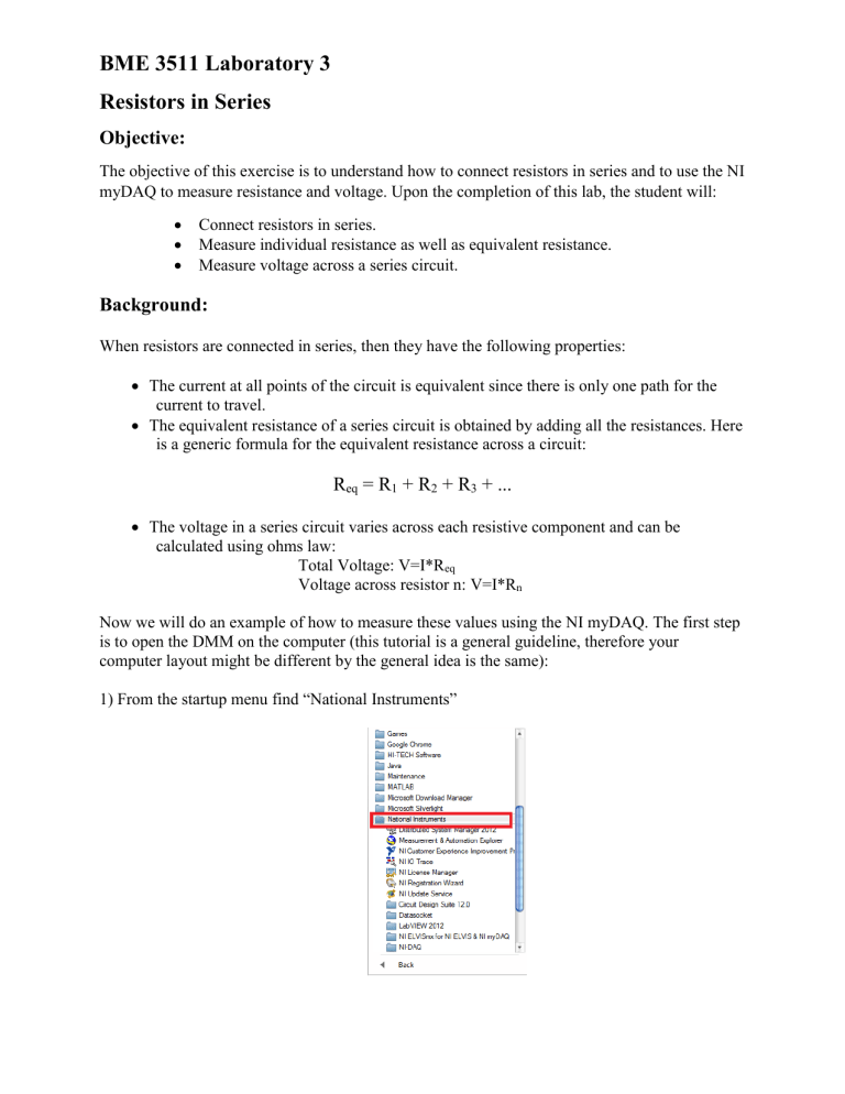
1) From the startup menu find “National Instruments”
2) After the dropdown menu is opened, click on “NI ELVISmx for NI ELVIS & NI myDAQ”.
3) Click on “NI ELVISmx Instrument Launcher”.
4) The following window should open and since we want the digital multimeter( DMM) click on the DMM icon.
5) You should get the DMM apparatus as shown below.
6) Since we want to measure resistance, switch the DMM from voltage to resistance (Ω).
7) In the next step, for the Mode we select “Auto”, for Device select (“myDAQ1(NI myDAQ)”) and for Acquisition mode select “Run Continuously”.
8) The subsequent step is to connect the myDAQ to the computer via the USB cable. You should see the LED light up on the myDAQ as shown below.
9) Now we must connect the breadboard to the NI myDAQ. Make sure you hear a click when the pins fit into place. Your setup should look similar to the one shown below.
10) Next, we must connect the leads into the correct ports. The RED pin should be connected into the port with the VΩ symbol on it. The BLACK pin should be connected into the COM port.
11) After the you have connected everything, your setup should look similar to the one presented below:
12) Now we will set up the resistors on the breadboard in series; notice where each leg of the resistor is placed.
13) Next we will connect the circuit to the NI myDAQ, which will also serve as a 5 Volt power source in this example.
14) Next we will measure the resistance across each of the resistor and the resistance of both of the resistors in series. NOTE: You must measure the resistance of while the voltage source is powered off.
15) For the next measurement we will measure voltage by switch the DMM to the voltage setting and then measuring individual volatge through each resistor as well as the overall voltage.
Note: You should perform hand calculations before taking the measurements to get an approximate range. Also measurement of the voltage is same as resistance in terms of placing the probes on the resistors. In this case the DMM read the voltage across both resistors as the same and even though the total voltage was not equal to 5 V, it was close enough.


