PQE203 - B
Electrical Services
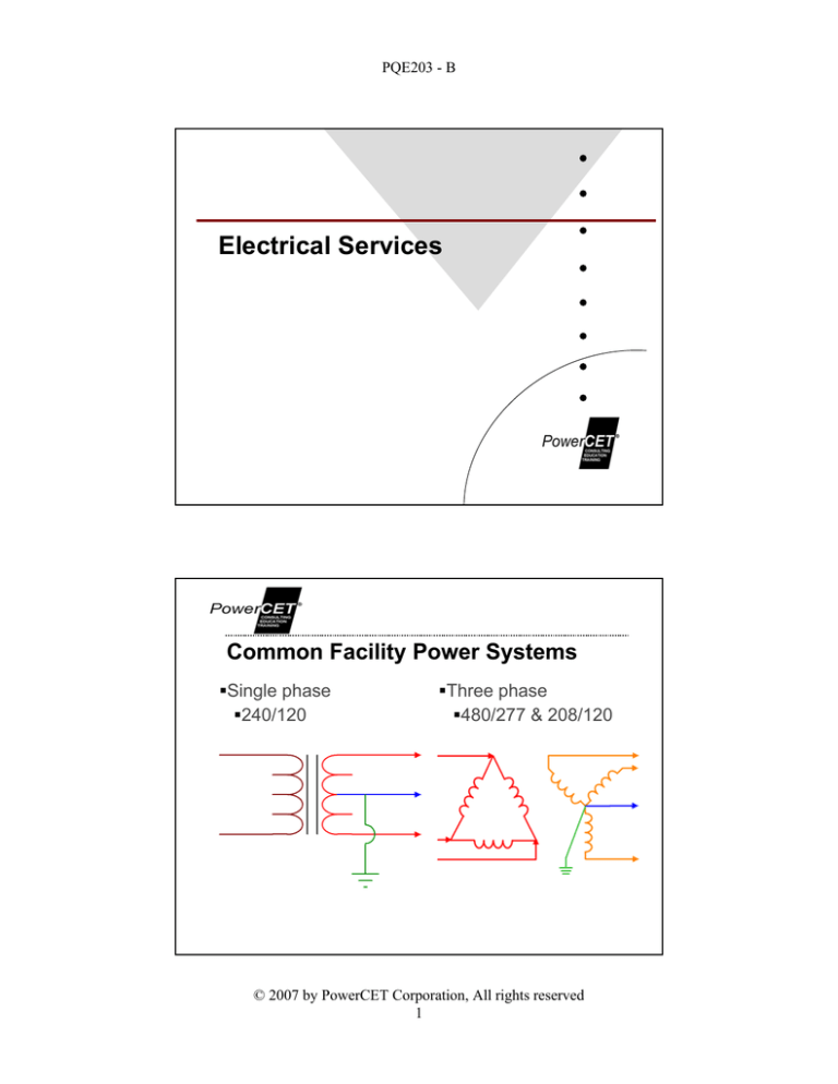
Common Facility Power Systems
Single phase
240/120
Three phase
480/277 & 208/120
© 2007 by PowerCET Corporation, All rights reserved
1
PQE203 - B
Common & Problematic Service
Three phase delta voltages (240 delta)
Single phase voltages (240/120)
High leg delta (crazy leg, red leg etc.)
Power/Grounding Variations
Floated wye
–Ground referenced voltages
vary with leakage currents
Floated delta-delta
–Ground referenced voltages
vary with leakage currents
Corner grounded delta
–One leg at earth potential,
others at phase-to-phase
potential
© 2007 by PowerCET Corporation, All rights reserved
2
PQE203 - B
Floated Delta-Delta Service
Absence of solid ground reference allows ground referenced
voltage fluctuations
–Load related fluctuations usually within voltage envelope of service
–Utility related fluctuations reflect primary voltages
–Lightning transients create severe dv/dt
Earthing/Grounding Variations
High-impedance grounded neutral systems
–NEC 250-36 [1999-2005]
–Typically resistive but may be resonant or inductive
–480 to 1000Vac three phase systems with No line-to-neutral loads
–Ground fault detection required
–Impedance sized to prevent arcing faults
–Neutral-to-ground bond sized for maximum current per the grounding impedance
(ANSI/IEEE 142-1991 Green Book)
–Equipment bonding jumper (from equipment grounding conductors to the grounding
impedance) shall be sized per 250.66 or 250.36B.
© 2007 by PowerCET Corporation, All rights reserved
3
PQE203 - B
Line-to-Ground 1 Ohm Short Test
One Ohm short to ground on output
of transformer
–Solid grounding
–Resistive grounding
–Inductive grounding
–Tuned tank grounding
Phase with short approaches zero
volts
Phases without short increase
(residual phase voltage plus ground
referenced voltage)
Large phase angle variations
Line-to-Ground Short Test
Solid
Ground
Phases
W/O Short
5 Ohm
Resistive
109 & 103 170 & 167
Phase
With Short
10mH
Inductive
180 Hz
Tank
192 & 146
197 & 153
72
17
34
30
N/G
Voltage
0.39
85
89
114
Fault
Current
75A
17A
36A
37A
© 2007 by PowerCET Corporation, All rights reserved
4
PQE203 - B
Line-to-Ground Short - Inductive Load
Ugly Voltage Sag & Transients
© 2007 by PowerCET Corporation, All rights reserved
5
PQE203 - B
Wye-to-Wye Services
Facility transformers
Utility systems
H
H
High
Low
Voltage
Voltage
N
N
G
HELP
ME
?????
DATA LINK
Transferred Earth Potential
Transferred Earth Potential (TEP)
–IEEE Std 142-1991 (Green Book)
ySections 1.6.4; 1.6.7; & 4.2.6
–Wye-to-Wye & 240/120
yPadmount applications prone to TEP
H
H
High
Low
Voltage
Voltage
N
Equipment
N
V
G
V
© 2007 by PowerCET Corporation, All rights reserved
6
PQE203 - B
TEP Case History
TEP; Lightning Two Miles Distant
© 2007 by PowerCET Corporation, All rights reserved
7
PQE203 - B
Generator Grounding
Continual Neutral Generator Setup
Not separately derived
3 Pole ATS
–Automatic transfer switch
GES
–Grounding electrode system
© 2007 by PowerCET Corporation, All rights reserved
8
PQE203 - B
Switched Neutral Generator Setup
Separately derived
4 Pole ATS
–Automatic transfer switch
GES
–Grounding electrode system
Distribution Grounding
Feeders
Transformers
Separately derived sources
Branch circuit wiring
© 2007 by PowerCET Corporation, All rights reserved
9
PQE203 - B
Feeder Grounding
Permanent, Continuous, & Contiguous
Ampacity sufficient for fault currents
–Conductors
–Raceway
–Conduit
Grounding Conductor Sizing
Article 250-122 [NEC 1999 - 2005]
–Wire size (AWG) tied to overcurrent protection (A)
–If circuit length requires larger conductors, then grounding conductor
size must also increase proportionally
–In a parallel circuit each grounding conductor must be fully sized per
the overcurrent protection for that parallel circuit
–Table 250-122 conductor sizing
y15A
y20A
y100A
y1000A
= 14 cu or 12 al
= 12 cu or 10 al
= 8 cu or 6 al
= 2/0 cu or 4/0 al
© 2007 by PowerCET Corporation, All rights reserved
10
PQE203 - B
Parallel Feeders (1)
NEC
–NEC 310-4 (1996 - 2005)
–Symmetrical
–Prevent objectionable ground current
–Use same material for conductors
–Use same material for
conduits/raceways
–Maintain same lengths
–Use proper conductor placement
–1/0 and larger
–Grounding conductor sizing
yNEC 250-122 (1999-2005)
Parallel Feeders (2)
© 2007 by PowerCET Corporation, All rights reserved
11
PQE203 - B
Separately Derived Sources
NEC 250-26 [1996]
NEC 250-30 [1999 & 2005]
–Transformers, UPS equipment, Motor generators
Figure status
–A = Not Separate -- Neutral is continuous
–B = Separately derived -- Neutral not continuous
Bonding
–Steel is preferred - NEC 250.30(A)(4) [2002]
–Water pipes not preferred unless metal pipes are
continuous and maintained
–Bonding to water pipes in areas served
yNEC 250.104(A)(4) [2002-2005]
Fault Clearing
Primary Fault
Secondary Fault
Vfault
Vfault
Vref
© 2007 by PowerCET Corporation, All rights reserved
12
PQE203 - B
Common Grounding Electrode
In facilities lacking structural steel or continuous, metal water piping, a
common grounding electrode may be used for separately derived equipment
-- NEC 250.30(A)(3) [2002] & NEC 250.30(A)(4) [2005]
Conductor sizing -- NEC 250.30(A)(2)(b) [2002]; NEC 250.66; Table 250.66
[2002]; NEC 250.30(A)(2) [2005]; NEC 250.102 [2005] - minimum size per
2005 code is 3/0 AWG copper.
Ground Fault Detection
© 2007 by PowerCET Corporation, All rights reserved
13
PQE203 - B
Ground Fault Circuit Interrupt
Protection for personnel: NEC 210-8 [1996 - 2005]
–32 separate references in the 2002 code & 39 references in 2005 code.
–Receptacles, portable devices, bathrooms, etc.
y5mA response level
SHUNT
TRIP
GFI SENSE
TEST
Facility Ground Fault Protection
Service entrance
–Protection for switchgear
yNEC 230-95 [1996 - 2005]
y>1000 ampere & >150V L-G
yMaximum response levels: 1200 amperes & 1 second
ySlowest and highest response levels at service entrance
Exceptions
–Service entrances with multiple input breakers (six or less) none of which have ampacities
equal to or greater than 1000 amperes.
–Continuous industrial services where the interupption of power poses more hazard than relying
upon normal overcurrent interruption
–Services with high impedance grounded neutral systems.
Emergency services
–Interrupt not required; NEC 700.26 [1996-2005]
–Visual and audible signal required; NEC 700-7(d) [1996 & 1999 & 2002]
y>1000 ampere & >150V L-G
yMaximum response 1200 amperes
© 2007 by PowerCET Corporation, All rights reserved
14
PQE203 - B
Ground Fault Interrupt 1
Polyphase -- single CT GFI -- "zero sequence"
SHUNT
TRIP
GFI SENSE
Ground Fault Interrupt 2
Polyphase -- Multiple CT GFI -- "residual"
SHUNT
TRIP
GFI SENSE
© 2007 by PowerCET Corporation, All rights reserved
15
PQE203 - B
Ground Fault Interrupt 3
Neutral-to-ground bond detect - "source"
SHUNT
TRIP
GFI SENSE
GFI Problems
Magnetic pickup from adjacent circuits
Voltage and current harmonics vs CT response
EMI/RFI sensitivity
Trips settings too low for the application
GFI on primary of N/G bond in wye-to-wye systems
Neutral return current flow through N/G bond CT in
multiple grounding systems
© 2007 by PowerCET Corporation, All rights reserved
16
PQE203 - B
Equipment Grounding
Equipment Grounding
NEC 250-42 [1996] & NEC 250-110 [1999] & NEC 250VI [2002]
–Effectively grounded
y NEC 250-51 [1996] & NEC 250-2 [1999] & NEC 250.136 [2002]
–Continuous & Contiguous - Capacity to safely conduct fault current
–Limit voltage to ground (touch potential) - Ensure rapid fault clearing
NEC 250.4(A)(5) Effective Ground-Fault Current Path
–"Electrical equipment and wiring and other electrically conductive material likely to
become energized shall be installed in a manner that creates a permanent, lowimpedance circuit facilitating the operation of the overcurrent device or ground
detector for high-impedance grounded systems. It shall be capable of safely
carrying the maximum ground-fault current likely to imposed on it from any point on
the wiring system where a ground fault mayu occur to the electrical supply source.
The earth shall not be considered as an effective ground-fault current path."
© 2007 by PowerCET Corporation, All rights reserved
17
PQE203 - B
Equipment Performance Issues
Complications
–Equipment reference
–Leakage current
–DC common & ac ground
–Induced chassis potentials
Grounding Discontinuity
Neutral/Ground Voltage
Leakage current
Grounding discontinuity
Chassis voltage
Data loss
Equipment reset
© 2007 by PowerCET Corporation, All rights reserved
18
PQE203 - B
Connection Quality
Connections become loose
with age
Screw connections
Too loose -- bad
Too tight -- bad
Proper torque -- rare
Grounding wire essential
Equipment Emissions
High frequency
emissions
–Pulse width modulation
–Power factor correction
–Clock/logic circuits
–I/O circuits
–Intentional RF use
FCC limits
–Class A (commercial)
–Class B (residential)
–9kHz and higher
y450kHz is the lower measurement
level
y127dBuV = 2.24Vrms
© 2007 by PowerCET Corporation, All rights reserved
19
PQE203 - B
High Frequency Leakage Current
Kirchoff's Laws prevail
–Pulse width modulation (PWM) Noise
–Power factor correction (PFC) Noise
Skin effect & inductance dominate
Ground is a path, not the terminus
s
2
I R
SELF INDUCTANCE
SKIN
EFFECT
Flexible Wiring Systems
Intended use
Limited length, voltage and ampacity
Usual use - lighting circuits
Types
FMC - Flexible metalic conduit NEC 348
[2005]
FMT - Flexible metalic tubing NEC 360
[2005]
Metal Clad (MC) NEC 330 [2005]
Grounding
NEC 250-118 [1999 -2005]
If not listed for grounding
6 feet length (1.83m)
Less than 20 amperes
© 2007 by PowerCET Corporation, All rights reserved
20
PQE203 - B
Equipment Leakage Current
UL limits
–3.5mA power frequencies
–Formerly 0.5 mA to 5mA
–Portable, cord connected devices
Circuit Testers
–2mA maximum
–Read & follow instructions!
–Disconnect loads before use
Sources
–Capacitive coupling
–Wiring errors
–I/O circuits
Receptacle Orientation
NEC
No specified position
IEEE White Book
IEEE Std. 602-1996
Section 4.2.2
"Ground pin or neutral blade
up"
Reduces accidental contact
with exposed live contacts.
© 2007 by PowerCET Corporation, All rights reserved
21
PQE203 - B
Randomly Placed Raceway Wiring
NEC 300.20 Induced currents in metal
enclosures or metal raceways [2005]
–"Where conductors carrying alternating current are installed in metal
enclosures or metal raceways, they shall be arranged so as to avoid
heating the surrounding metal by induction. To accomplish this, all
phase conductors and, where used, the grounded conductor and all
equipment grounding conductors shall be grouped together."
Conductor Types
Cable 1 = NEC/MC
3 phase, 3 grounds, no shield, aluminum interlocked
Cable 2 = NEC/TC
3 phase, 3 grounds, no shield, no armor, tray cable
Cable 5 = NEC/MC
3 phase, 3 ground, copper tape spiral shield,
galavanized steel interlocked
Cable 6 = IEC/MCMK
Cable 3 = NEC/MC
3 phase sectored symmetrical, no grounds, copper
tape & wire shield, no armor
3 phase, 3 grounds, no shield, galvanized interlocked
steel
Cable 7 = IEC/MCMK
Cable 4 = NEC/MC
IEC 3 phase sectored symmetrical, 1 ground, copper
tape & wire shield, no armor
3 phase, 1 ground, no shield, aluminum continuous
Cable 8 = NEC/MC
3 phase, 3 grounds, no shield, aluminum continuous
© 2007 by PowerCET Corporation, All rights reserved
22
PQE203 - B
Symmetrical Cable Variations
Equal inductive coupling
Magnetic field
Equal capacitive coupling
Electric field
Shielding controls common
mode emissions
400Hz applications require
symmetrical cabling
Parity Ground Conductor Sizing
Parity sizing
–Grounding conductor the same size as
current carrying conductors
–Not a code requirement
–Normally a vendor requirement
–Attempt to improve equipment reference
–Larger conductor size
yMay magnetically or capacitvely couple
yUse may increase ground current
A
B
G
C
N
A
N
G
B
C
© 2007 by PowerCET Corporation, All rights reserved
23
PQE203 - B
Parity Sizing Problem
Reference Grounding
Computer rooms
Raised floor environments
Data processing centers
© 2007 by PowerCET Corporation, All rights reserved
24
PQE203 - B
A Tale of Two Towers
500MCM conductors added to "improve reference"
Added grounding adversely affected equipment
Interference Signals in Equipment Wiring
Federal Information Processing Standards Publication
–FIPS PUB 94 -- 1983 September 21 -- Now discontinued
–US Department of Commerce - National Bureau of Standards
Guideline on Electrical Power for ADP Installations
© 2007 by PowerCET Corporation, All rights reserved
25
PQE203 - B
Ground Voltage Rise (200' Romex)
Tektronix
THS720
Surge
Generator
200
Feet
Receptacle
Ground Voltage Differentials
Tektronix
THS720
Receptacle
Surge
Generator
50
Feet
150
Feet
Receptacle
© 2007 by PowerCET Corporation, All rights reserved
26
PQE203 - B
Signal Reference Grid 1
A
Z
Z
B
TRANSIENT PLATE
REFERENCE GRID
HORIZONTAL STRINGERS
CONDUCTIVE CLIPS
Signal Reference Grid 2
FIPS PUB 94
4 AWG copper conductors -clamped intersections
Not a bad reference grid
1" metal braid and pedestal
clamps
A better reference grid
© 2007 by PowerCET Corporation, All rights reserved
27
PQE203 - B
4'x4' Reference Grid
SRG intersection points not bonded together
Less effective than would be with good connections.
Connections to Reference Grid
Short flat straps best
Metal braid OK
Bond at opposite corners
of equipment
Bond all equipment within
room
© 2007 by PowerCET Corporation, All rights reserved
28
PQE203 - B
Signal Reference Grid
A very good reference grid
Information Technology Rooms
Article 645 of NEC
–NEC 645-15 Grounding [1999 - 2005]
yPower systems that supply power through receptacles or cable assemblies
supplied as part of the system are not considered as separately derived.
ySignal reference systems must be bonded to the equipment grounding
system provided for the information technology room.
Recommended References
–NFPA 75-1995
yStandard for the Protection of Electronic Computer/Data Processing
Equipment
–IEEE Std. 1100-1992 -- Emerald Book
yIEEE Recommended Practice for Powering and Grounding Sensitive
Electronic Equipment
© 2007 by PowerCET Corporation, All rights reserved
29


