5-ramesh chourasia-brushless separately excited direct

ISSN 2321 – 2004
ISSN 2321 – 5526
I
NTERNATIONAL
J
OURNAL OF
I
NNOVATIVE
R
ESEARCH IN
E
LECTRICAL,
E
LECTRONICS,
I
NSTRUMENTATION AND
C
ONTROL
E
NGINEERING
Vol. 1, Issue 3, June 2013
Brushless Separately Excited Direct Current
Motor Electric Motors: A Survey
R.C.Chourasia
1
, Dr. A.K. Bhardwaj
2
Ph.D. Student in Electrical Engineering from SHIATS (formally Allahabad Agriculture, Institute, Allahabad) -India
1
Associate Professor and HOD in Electrical Engg. Department, SSET, SHIATS Allahabad India
2
Abstract: In this paper the importance of brushless SEDC electric motors in the automotive industry continues to grow, writes Matthew Beecham. The driving force behind market growth is motorists’ insatiable demand for safety, comfort, economy, a clean environment and overall quality of driving.
Keywords : BRUSHLESS SEDC (Separately Excited Direct Current) Motor, and Simulink.
I.INTRODUCTION
There are two kinds of SEDC motors: brush and brushless.
Brushless SEDC motors differ from conventional, brush
SEDC motors in that the current which produces mechanical energy is applied to stationary coils via electronic switches without physical contact with the rotor, rather than stationary rods brushing against the rotating coil [1 2]. The conventional brush SEDC motors have several limitations: brush life, brush residue, maximum speed and electrical noise [3 4]. By avoiding friction, sparks and the wearing and fragmenting of the brush rods, brushless SEDC motors provide cleaner, faster, more efficient and quieter operation and longer maintenance-free life than conventional brush
SEDC motors [5 6]. Although brushless SEDC motors have many advantages over brush SEDC motors the use of brushless SEDC motors is still mainly confined to precision applications in disc drives and industrial motion equipment that require high efficiency, smooth operation and precise speed control [7 8]. Besides standard brushless SEDC motors, mainly found in body and convenience areas of the vehicle, manufacturers report that brushless SEDC motors are already standard (for power steering and drives for hybrid vehicles) or will gain major importance [9].
The speed of separately excited DC [SEDC] motor can be controlled below the rated speed by using controlled rectifier as a converter. The controlled rectifier firing circuit receives signals from the controllers and then controlled rectifier gives variable voltage to the armature of the dc motor for achieve required speed. There are two control loops, first one for controlling current and another one for control of speed. Proportional-Integral [PI] type controllers are used, which removes the delay and provides fast control [10]. In this paper initially mathematical analysis of SEDC motor is performed followed by designing of current and speed controllers. Finally simulation model is developed to obtain the results.
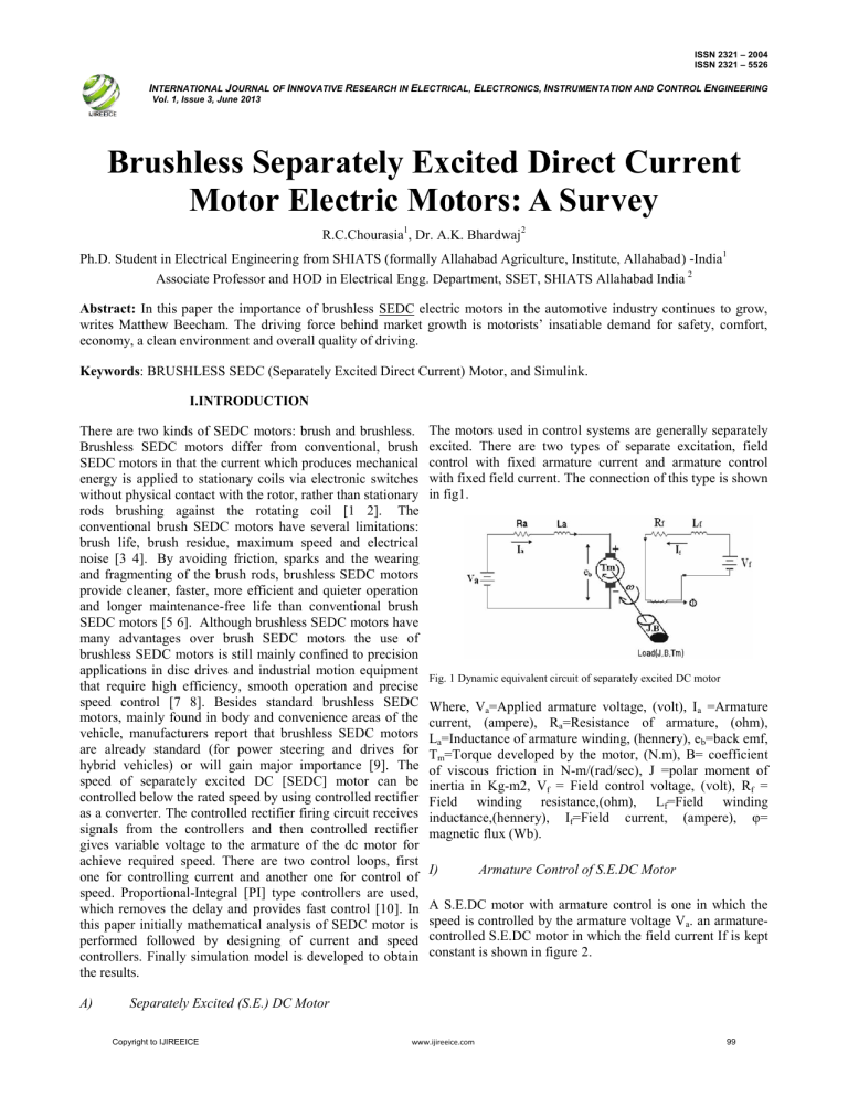
The motors used in control systems are generally separately excited. There are two types of separate excitation, field control with fixed armature current and armature control with fixed field current. The connection of this type is shown in fig1.
Fig. 1 Dynamic equivalent circuit of separately excited DC motor
Where, V a
=Applied armature voltage, (volt), I a
=Armature current, (ampere), R a
=Resistance of armature, (ohm),
L a
=Inductance of armature winding, (hennery), e b
=back emf,
T m
=Torque developed by the motor, (N.m), B= coefficient of viscous friction in N-m/(rad/sec), J =polar moment of inertia in Kg-m2, V f
= Field control voltage, (volt), R f
=
Field winding resistance,(ohm), L f inductance,(hennery), I f
=Field winding
=Field current, (ampere), φ= magnetic flux (Wb).
I) Armature Control of S.E.DC Motor
A S.E.DC motor with armature control is one in which the speed is controlled by the armature voltage V a
. an armaturecontrolled S.E.DC motor in which the field current If is kept constant is shown in figure 2.
A) Separately Excited (S.E.) DC Motor
Copyright to IJIREEICE www.ijireeice.com
99
ISSN 2321 – 2004
ISSN 2321 – 5526
I
NTERNATIONAL
J
OURNAL OF
I
NNOVATIVE
R
ESEARCH IN
E
LECTRICAL,
E
LECTRONICS,
I
NSTRUMENTATION AND
C
ONTROL
E
NGINEERING
Vol. 1, Issue 3, June 2013 good robustness is obtained by the proposed strategy. so that the controller parameter is optimized. The simulation results that the controller of the proposed method has a good adaptability and strong robustness when the system is disturbed, which is better than traditional PID control.
Fig. 2 Armature controlled of S.E.DC motor.
Where, R a
=Resistance of armature, (ohm), L a
= Inductance of armature winding, (hennery), I a
= Armature current,
(ampere), I f
= Field current, (ampere), V a
= Applied armature voltage, (volt), e b
= back emf, (volt), T m
=Torque developed by the motor, (N.m),θ=Angular displacement of motor-shaft, (radian), ω = Angular Velocity of motor-shaft,
J= Equivalent moment of inertia of motor and load referred to motor shaft, (Kg.m2), B=Equivalent viscous-friction coefficient of the motor and load referred to the motor shaft,
(N.m/rad/sec).
Fig. 4 Neural fuzzy speed control system of BLDCM
II) Field Control Of S.E.DC Motor
A separately excited (S.E.) DC motor in which the armature current I a
is maintained constant is shown in figure 3.
As novel high-accurate speed estimator using a recurrent
Wavelet Neural Network (WNN) is proposed and validated for BLDC motor drives. The experimental results show that the WNN speed estimator yields promising results over a wide operating range including low-speed bands and transient operating conditions. A recurrent WNN-based speed estimator for BLDC motors has been proposed. It was verified through simulations and validated through hardware experiments. The study results show that the WNN-based speed estimator provides accurate speed outputs over a wide speed operating range as well as in motor transient processes.
Speed estimated
Fig. 3 Field controlled of S.E.DC motor.
WNN
Where, R f
= Field winding resistance,(ohm), L f
= Field winding inductance,(hennery), V
(volt), T m f
= Field control voltage,
= Torque developed by the motor, (N.m), ω =
Angular velocity of the motor shaft, (rad/sec), θ = Angular displacement of motor-shaft, (radian), I a
= Armature current, (ampere), I f
= Field current, (ampere), The constant current I a
may be supplied by a DC generator or from an AC line. The latter method requires the use of transformers and rectifiers to obtain the proper rectification.
II.METHODOLOGICAL VIEW
As brushless DC motor (BLDCM) is a multivariable and non-linear system, using conventional PID control cannot obtain satisfied control effect. Based on the mathematic model of BLDCM, a fuzzy neural network controller is designed, and the membership function is composed by
Guass function. The system illustrates that excellent flexibility and adaptability as well as high precision and
PWM DC3AC
Input Signal
BLDC
Speed measured
Fig. 5 Block Diagram of the VTB (virtual test bed)
As Neuro Fuzzy Technique in estimating speed and controlling it for a separately excited DC motor. The rotor speed of the dc motor can be made to follow an arbitrarily selected trajectory. The purpose is to achieve accurate trajectory control of the speed of separately excited DC
Motor, especially when the motor and load parameters are unknown.
Copyright to IJIREEICE www.ijireeice.com
100
ISSN 2321 – 2004
ISSN 2321 – 5526
I
NTERNATIONAL
J
OURNAL OF
I
NNOVATIVE
R
ESEARCH IN
E
LECTRICAL,
E
LECTRONICS,
I
NSTRUMENTATION AND
C
ONTROL
E
NGINEERING
Vol. 1, Issue 3, June 2013
REFERENCES
Fig. 6 fuzzy logic controller for speed estimation
III.CONCLUSION
Due to the lack of data, definitive conclusions regarding the effects of disturbance performance are not good stable.
However, it is clear that the need of stability improvement for the performance of motor. Adverse effects are present more losses in industry application. Since the few published paper dose-response studies did not employ state of behavioral tests known to be sensitive to the effects of experimental treatments on stability performance, they may underestimate the adverse effects of motor. In addition, the tests used did not permit determination of the specific behavioral functions affected by disturbance.
[1] K. Iizuka, H. Uzuhashi, M. Kano, T. Endo and K. Mohri,
“Microcomputer control for sensorless brushless motor,”
IEEE Trans.
Industry Application , Vol. IA-21, May 1985.
[2] J.Shao, D.Nolan and T.Hopkins, “A novel direct back EMF detection for sensorless Brushless DC (BLDC) motor drives,” Proc. of the IEEE
Applied Power Electronic Conference , 2002.
[3] S. Ogasawara and H. Akagi, “An approach to position sensorless drive for brushless dc motors,”
Proc. of the IEEE Industry Applications Society
Annual Meeting ,1990.
[4] J. C. Moriera, “Indirect sensing for rotor flux position of permanent magnet AC motors operating in wide speed range,”
Proc. of the IEEE
Industry Applications Society Annual Meeting , pp. 401-407, 1994.
[5] B. Terzic and M. Jadric, “Design and implementation of the extended
Kalman filter for the speed and rotor position estimation of brushless DC motor”, IEEE Trans. Industry electronics , Vol. 48, Issue 6, pp. 1065-1073,
Dec. 2001.
[6] B. K. Bose, Modern power electronics and AC drives , Prentice Hall,
2001.
[7] Hui Lin, Rong Qi. “Study on Key Techniques for Electrical System of
More-Electric Aircraft”. Xi'an: Northwestern Polytechnic University ,
2001.8:7 ~ 11.
[8] Liming Yu. “Improved technology and its development of All-electric aircraft”.
Plane design , 1999,9. (3).
[9] Tongji Yao. “The All-electric aircraft and its electric power system”.
Foreign flight, 1988.
[10] Hui Lin, Rong Qi. “Electric Actuation System of More-Electric
Aircraft”.
Xi'an: Northwestern Polytechnic University , 2004,11
BIOGRAPHIES
Future studies should be conducted using both stability improvement and performance of motor. An accurate behavioral tests known to be sensitive to various industry and environmental factors, and that can assess specific behavioral functions, should be employed in such studies. In addition, a “positive” control should be included in such studies, such as different type controller with its properties.
A positive control will provide a metric for relating any effects of disturbance to a factor with a known stability to improve performance.
Ramesh Chandra Chourasia Allahabad received his
B.Tech. degree in Electrical Electronics Engineering from Birala Institute of Technology, Mesra, Ranchi. M.Tech in Electrical & Electronics
Engineering (Power System) from SHAITS (formally Allahabad
Agriculture, Institute, Allahabad India ) in 2012. Presently He is pursuing Ph.D. in Electrical Engineering from SHIATS (formally
Allahabad Agriculture, Institute, Allahabad -India).
Dr. A.K. Bhardwaj Allahabad, 16.01.1965,Received his Bachelor of
Engineering degree from JMI New Delhi in 1998; He obtained his
M.Tech. degree in Energy and Env. Mgt. from IIT New Delhi in 2005.
He completed his Ph.D in Electrical Engg. From SHIATS (Formerly
Allahabad Agriculture Institute, Allahabad- India) in 2010. He has published several research paper in the field of Electrical Engineering.
Presently he is working as Associate Professor and HOD in Electrical
Engg. Department, SSET, SHIATS Allahabad- India.
Copyright to IJIREEICE www.ijireeice.com
101


