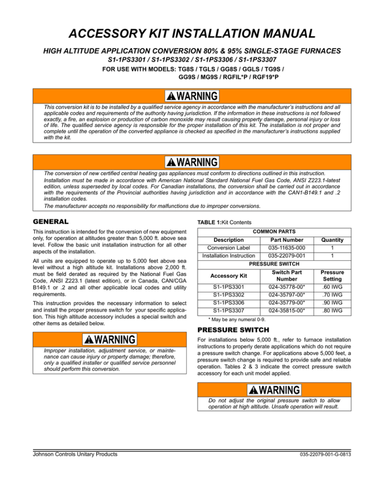
ACCESSORY KIT INSTALLATION MANUAL
HIGH ALTITUDE APPLICATION CONVERSION 80% & 95% SINGLE-STAGE FURNACES
S1-1PS3301 / S1-1PS3302 / S1-1PS3306 / S1-1PS3307
FOR USE WITH MODELS: TG8S / TGLS / GG8S / GGLS / TG9S /
GG9S / MG9S / RGFIL*P / RGF19*P
This conversion kit is to be installed by a qualified service agency in accordance with the manufacturer’s instructions and all
applicable codes and requirements of the authority having jurisdiction. If the information in these instructions is not followed
exactly, a fire, an explosion or production of carbon monoxide may result causing property damage, personal injury or loss
of life. The qualified service agency is responsible for the proper installation of this kit. The installation is not proper and
complete until the operation of the converted appliance is checked as specified in the manufacturer’s instructions supplied
with the kit.
The conversion of new certified central heating gas appliances must conform to directions outlined in this instruction.
Installation must be made in accordance with American National Standard National Fuel Gas Code, ANSI Z223.1-latest
edition, unless superseded by local codes. For Canadian installations, the conversion shall be carried out in accordance
with the requirements of the Provincial authorities having jurisdiction and in accordance with the CAN1-B149.1 and .2
installation codes.
The manufacturer accepts no responsibility for malfunctions due to improper conversions.
GENERAL
This instruction is intended for the conversion of new equipment
only, for operation at altitudes greater than 5,000 ft. above sea
level. Follow the basic unit installation instruction for all other
aspects of the installation.
All units are equipped to operate up to 5,000 feet above sea
level without a high altitude kit. Installations above 2,000 ft.
must be field derated as required by the National Fuel Gas
Code, ANSI Z223.1 (latest edition), or in Canada, CAN/CGA
B149.1 or .2 and all other applicable local codes and utility
requirements.
This instruction provides the necessary information to select
and install the proper pressure switch for your specific application. This high altitude accessory includes a special switch and
other items as detailed below.
Improper installation, adjustment service, or maintenance can cause injury or property damage; therefore,
only a qualified installer or qualified service personnel
should perform this conversion.
TABLE 1:Kit Contents
COMMON PARTS
Description
Conversion Label
Installation Instruction
Part Number
035-11635-000
035-22079-001
Quantity
1
1
PRESSURE SWITCH
Accessory Kit
S1-1PS3301
S1-1PS3302
S1-1PS3306
S1-1PS3307
Switch Part
Number
024-35778-00*
024-35797-00*
024-35779-00*
024-35815-00*
Pressure
Setting
.60 IWG
.70 IWG
.90 IWG
.80 IWG
* May be any numeral 0-9.
PRESSURE SWITCH
For installations below 5,000 ft., refer to furnace installation
instructions to properly derate applications which do not require
a pressure switch change. For applications above 5,000 feet, a
pressure switch change is required to provide safe and reliable
operation. Tables 2 & 3 indicate the correct pressure switch
accessory for each unit model applied.
Do not adjust the original pressure switch to allow
operation at high altitude. Unsafe operation will result.
Johnson Controls Unitary Products
035-22079-001-G-0813
s
TABLE 2:High Altitude Pressure Switch Usage 80% Furnaces
INPUT
(MBH)
OUTPUT
(MBH)
ACCESSORY
PART NUMBER
Upflow / Horizontal & Downflow/Horizontal Models
40
32
S1-1PS3301
60
48
S1-1PS3301
80
64
S1-1PS3301
100
80
S1-1PS3302
120
92
S1-1PS3301
130
104
S1-1PS3302
HIGH ALTITUDE KIT
PRESSURE SWITCH
LOCATION
TABLE 3:High Altitude Pressure Switch Usage 95% Furnaces
INPUT
(MBH)
OUTPUT
(MBH)
ACCESSORY
PART NUMBER
Upflow / Horizontal & Downflow/Horizontal Models
40
38
S1-1PS3307
60
57
S1-1PS3306
80
76
S1-1PS3307
100
95
S1-1PS3302
120
114
S1-1PS3302
130
123.5
S1-1PS3302
The high altitude pressure switch should be changed by following this procedure
FIGURE 1: Pressure Switch Location (80% Models)
.
1.
Remove the burner access door. Replace the pressure
switch in accordance with Figure 1 or 2 and the following
procedures.
2.
Note the location of the wires on the pressure switch and
then disconnect them. Remove the hose from the pressure
switch.
3.
Remove the screws securing the pressure switch and
remove it from the unit. Check that the new pressure switch
kit is correct for your application (Refer to “Pressure
Switch” Tables 2 & 3). Install the new pressure switch.
4.
Replace the hose and wiring as originally connected.
5.
Complete (fill-in) data as required on the conversion label.
Install label onto any section of furnace door or cabinet that
is accessible.
6.
Replace the burner access door.
HIGH ALTITUDE KIT
PRESSURE SWITCH
LOCATION
FIGURE 2: Pressure Switch Location (95% Models)
Subject to change without notice. Published in U.S.A.
Copyright © 2013 by Johnson Controls, Inc. All rights reserved.
York International Corp.
5005 York Drive
Norman, OK 73069
035-22079-001-G-0813
Supersedes: 035-22079-001-F-0413


