Electricity and Magnetism
advertisement

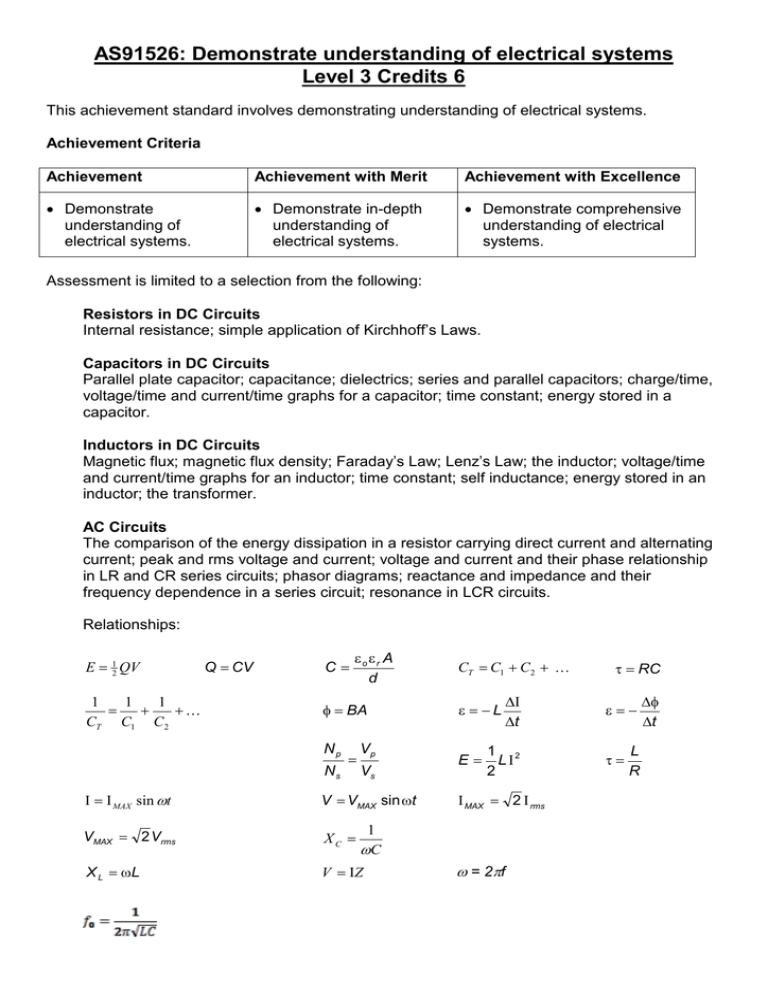
AS91526: Demonstrate understanding of electrical systems Level 3 Credits 6 This achievement standard involves demonstrating understanding of electrical systems. Achievement Criteria Achievement Achievement with Merit Achievement with Excellence • Demonstrate understanding of electrical systems. • Demonstrate in-depth understanding of electrical systems. • Demonstrate comprehensive understanding of electrical systems. Assessment is limited to a selection from the following: Resistors in DC Circuits Internal resistance; simple application of Kirchhoff’s Laws. Capacitors in DC Circuits Parallel plate capacitor; capacitance; dielectrics; series and parallel capacitors; charge/time, voltage/time and current/time graphs for a capacitor; time constant; energy stored in a capacitor. Inductors in DC Circuits Magnetic flux; magnetic flux density; Faraday’s Law; Lenz’s Law; the inductor; voltage/time and current/time graphs for an inductor; time constant; self inductance; energy stored in an inductor; the transformer. AC Circuits The comparison of the energy dissipation in a resistor carrying direct current and alternating current; peak and rms voltage and current; voltage and current and their phase relationship in LR and CR series circuits; phasor diagrams; reactance and impedance and their frequency dependence in a series circuit; resonance in LCR circuits. Relationships: E = 12 QV 1 1 1 = + + CT C1 C 2 Q = CV C= εo εr A d φ = BA Np Ns = Vp Vs Ι = Ι MAX sin ωt V = VMAX sin ωt VMAX = 2 Vrms XC = X L = ωL V = ΙZ CT = C1 + C 2 + ε = −L E= ∆Ι ∆t 1 2 LΙ 2 Ι MAX = 2 Ι rms 1 ωC ω = 2πf τ = RC ε=− τ= L R ∆φ ∆t Achievement criteria 1 Demonstrate understanding involves showing an awareness of how simple facets of phenomena, concepts, or principles relate to a given situation. Demonstrate in-depth understanding involves giving explanations for phenomena, concepts, or principles that relate to a given situation. Demonstrate comprehensive understanding involves connecting concepts or principles that relate to a given situation. 2 Electrical systems include mathematical solutions and/or written descriptions. Written descriptions may include graphs or diagrams. This achievement standard replaced unit standard 6389, unit standard 6390, and AS90523. This standard matches – virtually entirely – the content of the old standard AS90523. Achievement Make sure you can: • Identify or describe aspects of phenomena, concepts, or principles • Solve straightforward problems that involve a single-step process • Recognise correct concept/phenomenon/principle and give a simple descriptive answer in both written and diagrammatic form, for example: o the discharge of a capacitor in a closed circuit o that a capacitor takes five time constants to become fully charged or discharged o the effect of the resistance on the discharge current from a capacitor • Recognise the correct concept and apply reasonable mathematical skills, for example: o the relationship between angular and cyclic frequency o the relationship between inductor reactance and angular frequency Achievement with Merit Make sure you can: • Give accurate explanations in terms of phenomena, concepts, principles, and/or relationships • Solve problems that may involve using a complex formula or rearrangement or some deduction as to the relevant concept or principle • Use physics terminology to explain principles related to DC circuits and capacitance, as well as electromagnetic induction and AC circuits Achievement with Excellence Make sure you can: • Give concise and accurate explanations that show clear understanding in terms of phenomena, concepts, principles, and/or relationships. Your answers will typically have minimal irrelevancies. In other words, you cannot include any explanations that are not relevant. • Solve complex problems that will involve more than one process and concept • Show numerical accuracy and correct rounding, and use SI units in answers DC Circuits You should be able to: Use the formula R = V/I to calculate the resistance of a conductor. Use the formula P =IV to calculate the power used by a conductor. Add resistors in series and parallel Calculate the E.M.F and internal resistance of various voltage loops. Use Kirchhoff’s laws to calculate voltages and currents in one- and two-loop circuits, which may include DC voltage sources and resistors. Capacitors in DC Circuits You should be able to: Describe and explain the terms capacitance, the parallel plate capacitor, and dielectric. Describe the function of a capacitor in a DC circuit. Describe the relationship between variables affecting a parallel plate capacitor. Calculate the total capacitance for series and parallel capacitor combinations. Calculate the energy stored in a capacitor in terms of the area under the Q-V graph. Describe and explain capacitor charge/discharge curves (Voltage/time and current/time) in terms of accumulation of charge and comment on the meaning of the time constant. Inductors in DC Circuits You should be able to: Define the terms magnetic flux and magnetic field strength. Describe the factors affecting the magnetic field strength inside a solenoid. Describe the function of an inductor in a DC circuit. Describe and explain inductor charge/discharge curves (Voltage/time and current/time) and comment on the meaning of the time constant. Describe energy stored in an inductor. Describe and explain the relationship between rate of change of flux and the voltage induced across a conductor. Use Faraday’s Law to calculate the magnitude of the Induced voltage in a coil rotating with a constant angular velocity in a uniform magnetic field. Apply Lenz’s law to predict the direction of an induced current. Identify factors which affect the size and direction of the induced voltage of an inductor. Describe and explain the terms mutual and self- inductance. Describe and explain the factors which affect the size and direction of the induced voltage of an inductor. Describe and explain the relationship between primary (input) voltage/current and secondary (output) voltage/current in a transformer. AC Circuits You should be able to: Compare the energy dissipation of a resistor carrying DC and AC. Describe the difference between the RMS and peak values of current and voltage in an AC circuit. Describe that the current and voltage for a resistor in an AC circuit are in phase. Describe full and half wave rectification and smoothing in DC power supplies. Describe and explain why current leads p.d by 90o in a capacitor in an RC circuit. Describe and explain why current lags p.d by 90o in an inductor in an LR circuit. Describe and explain the terms reactance and impedance and their frequency dependence in a series circuit. Use equations and graphs to depict the phase and amplitude relationship of the current and voltages in an LCR series circuit. Describe and explain energy changes, phase relationships and the resonant condition for an inductor-capacitor-resistor series circuit. Describe and explain phasor diagrams to illustrate the relationship between Vtotal, VR, VL and VC in an AC LCR circuit. Use the resistance, capacitor reactance and inductor reactance to calculate the impedance of an LCR circuit. Describe and explain from phasors that the alternating current in an LCR series circuit will be at a maximum when VL = VC and use this observation to derive the resonant frequency equation f = 2Π√LC. Please note that the NCEA Sample paper had different equations as below: Sample paper equations


