laser- scan dia- gauge for fuel pellet diameter measurement
advertisement

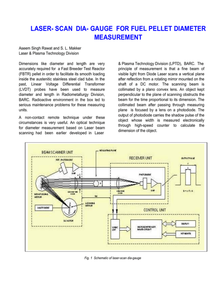
LASER- SCAN DIA- GAUGE FOR FUEL PELLET DIAMETER MEASUREMENT Aseem Singh Rawat and S. L. Makker Laser & Plasma Technology Division Dimensions like diameter and length are very accurately required for a Fast Breeder Test Reactor (FBTR) pellet in order to facilitate its smooth loading inside the austenitic stainless steel clad tube. In the past, Linear Voltage Differential Transformer (LVDT) probes have been used to measure diameter and length in Radiometallurgy Division, BARC. Radioactive environment in the box led to serious maintenance problems for these measuring units. A non-contact remote technique under these circumstances is very useful. An optical technique for diameter measurement based on Laser beam scanning had been earlier developed in Laser & Plasma Technology Division (LPTD), BARC. The principle of measurement is that a fine beam of visible light from Diode Laser scans a vertical plane after reflection from a rotating mirror mounted on the shaft of a DC motor. The scanning beam is collimated by a plano convex lens. An object kept perpendicular to the plane of scanning obstructs the beam for the time proportional to its dimension. The collimated beam after passing through measuring plane is focused by a lens on a photodiode. The output of photodiode carries the shadow pulse of the object whose width is measured electronically through high-speed counter to calculate the dimension of the object. Fig. 1 Schematic of laser-scan dia-gauge The diameter of the object is calculated according to the formula: d=(t/T)xD+offset; width. It consist of three parts: i) Beam Scanner unit. ii) Receiver unit. iii) Control unit. where d=diameter of the object, t=shadow pulse width, T=Aperture pulse width, D=Diameter of Aperture Offset –due to finite beam size An instrument has been developed using the above principle, viz LASER-SCAN DIA-GAUGE, and its technology transferred to two outside industries, viz 1)M/s Suresh Indu Lasers Pvt. Ltd, Pune, 2) M/s Jasch Industries Ltd, New Delhi. Using the same principle of laser beam scanning, a modified instrument has been developed at LPTD for measurement of fuel pellet diameter from outside the glass walled Glove Box of about one metre In Beam Scanner unit, a laser beam (from Diode Laser, 670 nm) scans a vertical plane after reflection from a rotating mirror mounted on the shaft of a DC motor (Fig 1). To save the horizontal space, the beam is folded by a mirror, after reflection from the scanner, towards collimating lens (a plano convex lens to collimate scanning beam). As the instrument is to be kept outside the glove box, the minimum separation between beam scanner unit and receiver unit is 1 metre. The object (fuel pellet) will be near the center of the glove box around 50 cm away from the beam scanner unit. The collimating lens is of 25 mm diameter and 500 Fig. 2 Beam scanner unit 1 Metre Fig. 3 Diameter measurement by laser meter mm focal length. In the laboratory, the unit has been tested with the separation between beam scanner unit and receiver unit being about 1 metre. Two glass plates similar to the glass walls of Glove Box have been kept in between the scanner and receiver unit with one plate near each unit. The Receiver unit consists of focusing lens and a photodiode-amplifier card. The lens focuses the incoming scanning beam onto a photodiode (Fig 1). The output of photodiode carries the shadow pulse of the object (fuel pellet). The amplifier output is fed to the control unit. The Control unit consists of schmitt trigger, logic circuit, counters, microcontroller (87c51), LCD and keyboard interface. The output of Receiver unit is passed through schmitt trigger and logic circuit to generate the Gating pulses for high speed (100 MHz) counters. At the end of each scan, the microcontroller reads the counter values corresponding to total pulse width (of aperture) and shadow pulse (of object) and calculates the diameter value. The value thus calculated is displayed on LCD. A keyboard is provided on the Control unit through which two functions are available to the user: i) Changing the number of Averages. By increasing the averaging figure, the measuring time is increased but it improves the accuracy/ repeatability. ii) Setting the lower and upper limit to sort out samples within acceptable range. A RS–232 serial interface is also provided to transfer the data (diameter value) to PC for data analysis. The specifications of the instrument are as follows: Measuring Range Accuracy Repeatability Scan Rate Measuring Time Laser : 5 mm to 20 mm : 10 micron : ±2 micro : 40 per second : 1 second : Diode Laser at 670 nm. The instrument has been tested for actual working conditions. It is now proposed to use two such instruments for diameter as well as length measurement of fuel pellet in a continuous on-line quality testing process. Based on the same principle of scanning, a multipoint diameter measuring system is under development using line scanning for simultaneous diameter measurement on 32 points along the length of a 100 mm long clad tube at 3 mm interval. The system has been designed using Laser line generator, line collimator, line canner, cylindrical collimating lens, cylindrical focusing lense, multiphotodiode card with amplifier, logic circuit cards, high speed counter PC add-on cards and Industrial PC. It will display the multi-point diameter values online on PC monitor and store these for further analysis purpose.


