vswr measurement with ferrite circulator ....................................... 16
advertisement
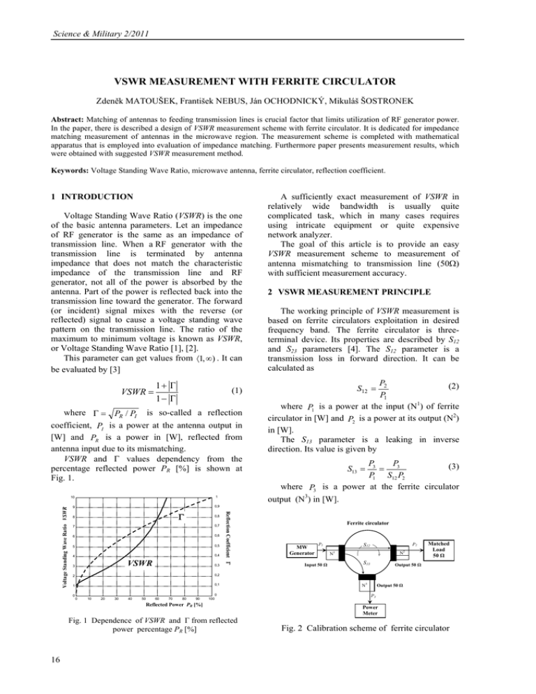
Science & Military 2/2011 VSWR MEASUREMENT WITH FERRITE CIRCULATOR Zdeněk MATOUŠEK, František NEBUS, Ján OCHODNICKÝ, Mikuláš ŠOSTRONEK Abstract: Matching of antennas to feeding transmission lines is crucial factor that limits utilization of RF generator power. In the paper, there is described a design of VSWR measurement scheme with ferrite circulator. It is dedicated for impedance matching measurement of antennas in the microwave region. The measurement scheme is completed with mathematical apparatus that is employed into evaluation of impedance matching. Furthermore paper presents measurement results, which were obtained with suggested VSWR measurement method. Keywords: Voltage Standing Wave Ratio, microwave antenna, ferrite circulator, reflection coefficient. 1 INTRODUCTION Voltage Standing Wave Ratio (VSWR) is the one of the basic antenna parameters. Let an impedance of RF generator is the same as an impedance of transmission line. When a RF generator with the transmission line is terminated by antenna impedance that does not match the characteristic impedance of the transmission line and RF generator, not all of the power is absorbed by the antenna. Part of the power is reflected back into the transmission line toward the generator. The forward (or incident) signal mixes with the reverse (or reflected) signal to cause a voltage standing wave pattern on the transmission line. The ratio of the maximum to minimum voltage is known as VSWR, or Voltage Standing Wave Ratio [1], [2]. This parameter can get values from ⟨1, ∞) . It can be evaluated by [3] VSWR = 1+ Γ 1− Γ (1) where Γ = PR / PI is so-called a reflection coefficient, PI is a power at the antenna output in [W] and PR is a power in [W], reflected from antenna input due to its mismatching. VSWR and Γ values dependency from the percentage reflected power PR [%] is shown at Fig. 1. 1 Γ 8 0,8 7 0,7 6 0,6 5 0,5 4 0,4 VSWR 3 0,3 2 0,2 1 0,1 0 0 0 10 20 30 40 50 60 70 80 90 100 Reflected Power PR [%] Fig. 1 Dependence of VSWR and Γ from reflected power percentage PR [%] 16 2 VSWR MEASUREMENT PRINCIPLE The working principle of VSWR measurement is based on ferrite circulators exploitation in desired frequency band. The ferrite circulator is threeterminal device. Its properties are described by S12 and S23 parameters [4]. The S12 parameter is a transmission loss in forward direction. It can be calculated as P2 (2) P1 where P1 is a power at the input (N1) of ferrite circulator in [W] and P2 is a power at its output (N2) in [W]. The S13 parameter is a leaking in inverse direction. Its value is given by S12 = P3 P (3) = 3 P1 S12 P2 where P3 is a power at the ferrite circulator output (N3) in [W]. S13 = 0,9 9 Reflection Coefficient Γ Voltage Standing Wave Ratio VSWR 10 A sufficiently exact measurement of VSWR in relatively wide bandwidth is usually quite complicated task, which in many cases requires using intricate equipment or quite expensive network analyzer. The goal of this article is to provide an easy VSWR measurement scheme to measurement of antenna mismatching to transmission line (50Ω) with sufficient measurement accuracy. Ferrite circulator MW Generator P1 Input 50 Ω P2 S12 N2 N1 S13 Matched Load 50 Ω Output 50 Ω N3 Output 50 Ω P3 Power Meter Fig. 2 Calibration scheme of ferrite circulator Science & Military 2/2011 The knowledge of above discussed parameters is the fundamental prerequisite of the accurate VSWR measurement. These parameters can be evaluated by proper calibration of ferrite circulators as is shown in Fig. 2. If S12 and S13 parameters in given frequency band are known, it is possible to do the VSWR measurement of unknown antenna [5]. In this article, the measurements of VSWR were done with microwave VSWR scheme that is shown in Fig. 3. The total reflection coefficient ΓSUM measured in this mode is given by P3M = P2 P3M , S12 P1 (7) where ΓMA is a reflection coefficient due to mismatch of the measured antenna. Anechoic Chamber VSWR measurement set Matched Load 50 Ω Calibration In the control computer, there is evaluated the power difference between values measured at the (N3) output of the ferrite circulator, in both modes of operation. This difference can be formulated by Measuring VSWR Computer control ΔP3 = P3M − P3C . MW Switch N2 (6) where the power ΔP3 is the power difference at the (N3) output of ferrite circulator due to mismatching of measured antenna. ΓSUM = ΓFC + ΓMA = Measured Antenna S13 P2 + ΔP3 , S12 P3 M = S13 P1 + ΔP3 = P2, ΔP2 Ferrite P3 Circulator N3 ΔP3 Power USB Port Meter By means of equations (5), (7) and (8) it is possible to yield the relationship for the reflection coefficient of measured antenna ΓMA PC Controller N1 ΓMA = P1 MW Computer control Generator The VSWR measurement works in the two mode of operating. In the first mode, the output of ferrite circulator (N2) is connected through microwave (MW) switch to matched load (50Ω.) If one to expects the zero attenuation and a perfect matching of MW switch, the value of the measured power P3C is evaluated by power meter and it is given by S13 P2 . S12 (4) In this mode, it can be figured out the reflection coefficient ΓFC of used ferrite circulator by ΓFC = P3C = P2 P3C . S12 P1 P3 M − P2 P3C = P2 ΔP3 = P2 ΔP3 . S12 P1 (9) By substitution of equation (9) into equation (1) it can be derived the relationship for the measured antenna VSWR Fig. 3 Circuit scheme of designed VSWR measurement site P3C = S13 P1 = (8) 1+ (10) This relationship is valid for measurements in which the power losses of transmission line (LC = POUT /PINP) can be neglected. If one uses the loss transmission line (a few meters long cable) it is necessary to consider these losses. For this case, the equation (9) changes to ΓMA = (5) The second mode of the VSWR measurement is a VSWR measurement of unknown antenna. If one can suppose the zero attenuation and perfectly matched MW switch, the value of measured power P3M that is evaluated by power meter is given by ΔP3 P2 ΔP3 S12 P1 . = VSWR = ΔP3 ΔP3 1− 1− P2 S12 P1 1+ ΔP3 2 C P2 L = ΔP3 S 12 P1 L2C . (11) Similarly to this operation the equation (10) changes into 1+ ΔP3 P2 L2C 1− ΔP3 P2 L2C VSWR = ΔP3 S12 P1 L2C . = ΔP3 1− S12 P1 L2C 1+ (12) 17 Science & Military 2/2011 3 MEASUREMENT RESULTS According to the functional diagram in Fig. 3 and with utilization above listed equations, there was realized microwave VSWR measurement with the PE 8400 ferrite circulator. For evaluation of power levels at (N3) output of ferrite circulator it was used power meter Anritsu MA24106A. Considering the frequency band of used ferrite circulator, the measurements was done in L-band (1 000 to 2 000 MHz). The S12, S13 parameters and VSWR of ferrite circulator after its calibration are given in Figs. 4 and 5. Parameters of Ferrite Circulator PE 8400 1.1 0.9 S12 S - Parameters 0.7 0.5 0.3 S13 0.1 -0.1 1000 1200 1400 1600 1800 2000 Frequency [MHz] Fig. 4 Measured parameters S12 and S13 of used ferrite circulator This emission is consequently reflected by the near surroundings of antenna. From above listed reasons it is necessary to place the measured antenna into anechoic chamber during measurements. Fig. 6, presents results of VSWR measurement of a conical helix-antenna which was designed for the frequency band of the Thuraya system. 4 CONCLUSIONS All measurement procedure is controlled by master computer using Matlab® environment. The results of VSWR measurement can be shown in the graphical or tablet form. Practical experiences showed, that it is necessary to optimize power levels at the ferrite circulator output (N1). The reason is to provide sufficient power levels during the P3M and P3C power level measurements at the output of ferrite circulator. Considering standard values of S13 parameter of available ferrite circulators (≈ -20 dB), the optimum power level from the generator is min. 1 mW up to 10 mW. The VSWR measurements was done for unknown and known certified antennas. The results confirm correctness of the designed method. VSWR vs. Frequency of Ferrite Circulator PE 8400 References 1.6 1.4 1.2 VSWR 1 0.8 0.6 0.4 0.2 0 1000 1200 1400 1600 1800 2000 Frequency [MHz] Fig. 5 VSWR graph of PE 8400 ferrite circulator The accuracy of realized measurements is significantly influenced by parasitic electromagnetic emission that surrounds the measured antenna. It includes the primary excitation emission from generator, too. Assoc. Prof. Dipl. Eng. Zdeněk MATOUŠEK, PhD. Armed Forces Academy of general M. R. Štefánik Demänová 393 031 01 Liptovský Mikuláš Slovak Republic E-mail: zdenek.matousek@aos.sk VSWR of Helix Antenna 2 1.9 1.8 1.7 VSWR [1] RICHARDS, R., D.: VSWR or Volting Standing Wave Ratio. [Online] Cited 2011-01-15. Available at: http://emc.toprudder.com/ vswr.pdf [2] MAZANEK, M., PECHAC, P., VOKURKA, J.: Anteny a sireni vln. 1st ed, CVUT Praha, 1998 (in Czech). [3] SOMEDA, G., C.: Electromagnetic Waves. 2nd ed, Taylor & Francis Group, Boca Raton, 2006. [4] TIRPAK, A: Elektronika velmi vysokych frekvencii. Comenius University, Bratislava, 2001 (in Slovak). [5] HICKMAN, I.: Practical Radio – Frequency Handbook. Elsevier, 1988. 1.6 1.5 1.4 1.3 1.2 1.1 1 1500 1520 1540 1560 1580 1600 1620 1640 1660 1680 1700 Frequency [MHz] Fig. 6 VSWR of conical helix antenna measured by ferrite circulator VSWR measurement 18 Assoc. Prof. RNDr. František NEBUS, PhD. Armed Forces Academy of general M. R. Štefánik Demänová 393 031 01 Liptovský Mikuláš Slovak Republic E-mail: frantisek.nebus@aos.sk Science & Military 2/2011 Assoc. Prof. Dipl. Eng. Ján OCHODNICKÝ, PhD. Armed Forces Academy of general M. R. Štefánik Demänová 393 031 01 Liptovský Mikuláš Slovak Republic E-mail: jan.ochodnicky@aos.sk Dipl. Eng. Mikuláš ŠOSTRONEK, PhD. Armed Forces Academy of general M. R. Štefánik Demänová 393 031 01 Liptovský Mikuláš Slovak Republic E-mail: mikulas.sostronek@aos.sk 19
