DSP Channel Card - Applied Micro Design, Inc.
advertisement

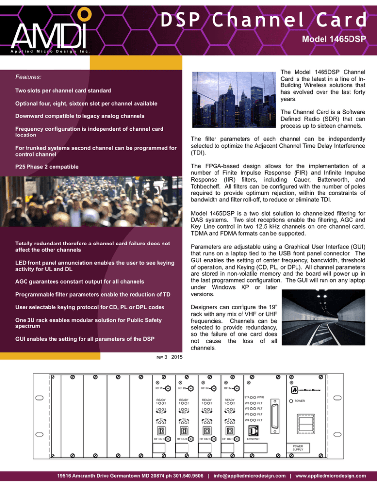
DSP Channel Card Model 1465DSP A p p l i e d M i c r o D e s i g n I n c . The Model 1465DSP Channel Card is the latest in a line of InBuilding Wireless solutions that has evolved over the last forty years. Features: Two slots per channel card standard Optional four, eight, sixteen slot per channel available The Channel Card is a Software Defined Radio (SDR) that can process up to sixteen channels. Downward compatible to legacy analog channels Frequency configuration is independent of channel card location The filter parameters of each channel can be independently selected to optimize the Adjacent Channel Time Delay Interference (TDI). For trunked systems second channel can be programmed for control channel The FPGA-based design allows for the implementation of a number of Finite Impulse Response (FIR) and Infinite Impulse Response (IIR) filters, including Cauer, Butterworth, and Tchbecheff. All filters can be configured with the number of poles required to provide optimum rejection, within the constraints of bandwidth and filter roll-off, to reduce or eliminate TDI. P25 Phase 2 compatible Model 1465DSP is a two slot solution to channelized filtering for DAS systems. Two slot receptions enable the filtering, AGC and Key Line control in two 12.5 kHz channels on one channel card. TDMA and FDMA formats can be supported. Totally redundant therefore a channel card failure does not affect the other channels Parameters are adjustable using a Graphical User Interface (GUI) that runs on a laptop tied to the USB front panel connector. The GUI enables the setting of center frequency, bandwidth, threshold of operation, and Keying (CD, PL, or DPL). All channel parameters are stored in non-volatile memory and the board will power up in the last programmed configuration. The GUI will run on any laptop under Windows XP or later versions. LED front panel annunciation enables the user to see keying activity for UL and DL AGC guarantees constant output for all channels Programmable filter parameters enable the reduction of TD Designers can configure the 19” rack with any mix of VHF or UHF frequencies. Channels can be selected to provide redundancy, so the failure of one card does not cause the loss of all channels. User selectable keying protocol for CD, PL or DPL codes One 3U rack enables modular solution for Public Safety spectrum GUI enables the setting for all parameters of the DSP rev 3 2015 RF IN RF IN RF IN A RF IN PPLIED MICRO DESIGN READY 1 2 READY 1 2 READY 1 2 READY 1 2 1 1 1 1 1 2 2 2 2 RX RX RX RX TX TX TX TX RF OUT 2 1 RF OUT 2 1 RF OUT 2 1 RF OUT 2 STA PWR W1 FLT W2 FLT W3 FLT W4 FLT POWER ETHERNET POWER SUPPLY 19516 Amaranth Drive Germantown MD 20874 ph 301.540.9506 | info@appliedmicrodesign.com | www.appliedmicrodesign.com The Model Number has the format outlined below. 1465DSP-C-S-P -3 dB BW where C is the number of Channel Cards (1 to 6) S is the number of Power Supplies (1 or 2) P indicates Processor Card (P or blank) For example, Model 1465DSP-4-2-P has four channel cards, two power supply cards, and a Processor Card installed in the chassis. -50 dB BW Specifications (all parameters are software defined) Frequency Range ** Number of Channels Channel Bandwidth Channel Spacing RF Frequency Accuracy Adjacent Channel Selectivity Time Delay Variation of Output Power with Input Level AGC Time Constant AGC Control Range Maximum passband Ripple (Full Band) Maximum Passband Ripple (Segment) IP3 Keying Duty Cycle Operating Temperature Range Input / Output Impedance Input / Output VSWR Input / Output Connectors Input Power Downlink Uplink 453 - 454 MHz 458 - 459 MHz 460 - 461 MHz 455 - 456 MHz 464 - 465 MHz 469 - 470 MHz 470 - 471 MHz 473 - 474 MHz 2 (standard); optional 4, 8, 16 available 12.5 kHz or 25 kHz 12.5 kHz or 25 kHz tracks input signal exactly 50 dB @ +/- 17.5 kHz < 60 microseconds +0, -1.0 dB in either direction < 100 microseconds + 80 dB 2 dB (across full band) 0.1 dB (across any 100 kHz segment) +20 dBm PL, DPL, Carrier-Detect (computer control) Continuous -20 oC to +60 oC 50 Ohms 1.35:1, worst-case SMA 95 - 132 VAC, 45 - 64 Hz ** - VHF, 800 MHz, and 900 MHz also available A p p l i e d M i c r o D e s i g n I n c . 19516 Amaranth Drive Germantown MD 20874 ph 301.540.9506 | info@appliedmicrodesign.com | www.appliedmicrodesign.com


