data sheet data sheet - National Model Railroad Association
advertisement

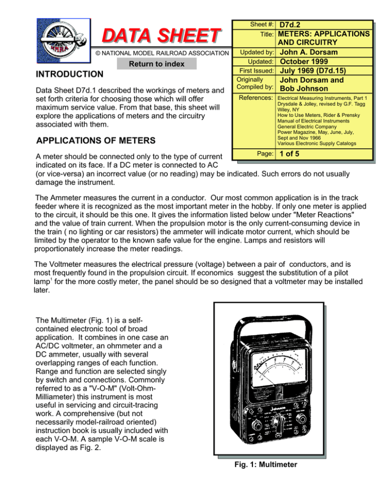
DATA SHEET © NATIONAL MODEL RAILROAD ASSOCIATION Return to index INTRODUCTION Data Sheet D7d.1 described the workings of meters and set forth criteria for choosing those which will offer maximum service value. From that base, this sheet will explore the applications of meters and the circuitry associated with them. APPLICATIONS OF METERS Sheet #: D7d.2 Title: METERS: APPLICATIONS Updated by: Updated: First Issued: Originally Compiled by: References: AND CIRCUITRY John A. Dorsam October 1999 July 1969 (D7d.15) John Dorsam and Bob Johnson Electrical Measuring Instruments, Part 1 Drysdale & Jolley, revised by G.F. Tagg Wiley, NY How to Use Meters, Rider & Prensky Manual of Electrical Instruments General Electric Company Power Magazine, May, June, July, Sept and Nov 1966 Various Electronic Supply Catalogs Page: 1 of 5 A meter should be connected only to the type of current indicated on its face. If a DC meter is connected to AC (or vice-versa) an incorrect value (or no reading) may be indicated. Such errors do not usually damage the instrument. The Ammeter measures the current in a conductor. Our most common application is in the track feeder where it is recognized as the most important meter in the hobby. If only one meter is applied to the circuit, it should be this one. It gives the information listed below under "Meter Reactions" and the value of train current. When the propulsion motor is the only current-consuming device in the train ( no lighting or car resistors) the ammeter will indicate motor current, which should be limited by the operator to the known safe value for the engine. Lamps and resistors will proportionately increase the meter readings. The Voltmeter measures the electrical pressure (voltage) between a pair of conductors, and is most frequently found in the propulsion circuit. If economics suggest the substitution of a pilot lamp1 for the more costly meter, the panel should be so designed that a voltmeter may be installed later. The Multimeter (Fig. 1) is a selfcontained electronic tool of broad application. It combines in one case an AC/DC voltmeter, an ohmmeter and a DC ammeter, usually with several overlapping ranges of each function. Range and function are selected singly by switch and connections. Commonly referred to as a "V-O-M" (Volt-OhmMilliameter) this instrument is most useful in servicing and circuit-tracing work. A comprehensive (but not necessarily model-railroad oriented) instruction book is usually included with each V-O-M. A sample V-O-M scale is displayed as Fig. 2. Fig. 1: Multimeter DATA SHEET © NATIONAL MODEL RAILROAD ASSOCIATION Sheet #: D7d.2 Title: METERS: APPLICATIONS AND CIRCUITRY Page: 2 of 5 APPLICATIONS OF METERS - continued Fig. 2: Multimeter Scale The V-O-M may be used to check for open circuits, short circuits and high-resistance connections. It will assist in identifying unmarked connectors in a cable or raceway. Permanently connected meters being rare in auxiliary circuits, the V-O-M will aid periodic checking of their pressure and current. It can be used to determine resistance values of coils, rheostats and resistors, and to some extent for checking capacitors. Its greatest value will probably be had as a self-contained continuity checker. Useful on almost any model railroad, it may become essential to the electrical group of a large club. Its value is limited only by the imagination and experience of the user. METER CIRCUITRY Ammeters must always be connected in series with the load. Note from Data Sheet D7n that it is correct to install the ammeter in the protected conductor, between protective device and load. Voltmeters must always be connected in parallel with the circuit to be measured. In Figs. 3 through 9, meters are conventional (zero left) unless marked (*), which indicates a zero-center instrument (note 1). Other abbreviations and symbols are these: A-Ammeter, V-Voltmeter, DC-Any Direct Current source, PP-Propulsion power pack, PS-Any power source. Note 1: A pilot lamp may furnish almost as much information as a voltmeter; at low voltages, the filament barely glows and lamp brilliance increases with applied voltage. A 28 V, lamp (No. 1819 or 1829) would burn less brightly than one of lower voltage, and a blue lamp cap might increase operator comfort. Connect pilot lamp same as voltmeter. DATA SHEET © NATIONAL MODEL RAILROAD ASSOCIATION Sheet #: D7d.2 Title: METERS: APPLICATIONS AND CIRCUITRY Page: 3 of 5 METER CIRCUITRY - continued Fig. 3: Meters connected to any power source, as for auxiliary circuits. Fig. 4: Optimum location of meters in custombuilt or commercially-available power packs. * * Fig. 5: Meters located between DC power source and direction controller as might be found when using a handheld or similar trackside control unit. Ammeter will read correctly but voltmeter will read source voltage only. Fig. 6: Meter located between direction controller and track, using hand-held or trackside control unit. Ammeter will read train current. Voltmeter will read track voltage. Both meters must be zero-center type because they are subject to polarity reversal. Fig. 7: Zero-center meter installed in conjunction with ready-to-use propulsion power pack, involving no other circuit changes. Fig. 8: Conventional meters employed in conjunction with ready-to-use propulsion power packs, with an additional direction controller applied. Original direction controller is no longer used. Preferable to Fig. 7. DATA SHEET © NATIONAL MODEL RAILROAD ASSOCIATION Sheet #: D7d.2 Title: METERS: APPLICATIONS AND CIRCUITRY Page: 4 of 5 METER SWITCHING At times it is desired to switch ammeters between two propulsion power packs. This may be done as shown in Fig. 9 but is generally less satisfactory than two separate meters and saves less money than might be expected. A zero-center type ammeter must be employed. When it is desirable to determine the current in a non-metered circuit, the system shown in Fig. 10 will be valuable; it embodies an ammeter (may need to be zero-center type in propulsion circuits), protective device, flexible leads and spring clips. When the spring clips are connected across an open circuit breaker or removed fuse, the current in that circuit will be indicated on the ammeter. Voltmeters may be switched among the various circuits. The system suggested by Fig. 11 is employed among accessory power circuits located in close proximity to each other. The diagram suggests plugs, but a selector switch is as good or better. No circuit Breaker is required in a voltmeter circuit. PACK "A" TRACK "A" PACK "B" TRACK "B" Figure 9 Figure 10 Figure 11 DATA SHEET © NATIONAL MODEL RAILROAD ASSOCIATION Sheet #: D7d.2 Title: METERS: APPLICATIONS AND CIRCUITRY Page: 5 of 5 METER REACTIONS Ammeter Reading High Zero Voltmeter Reading Low Problem Ammeter Reading Flickers low to normal Voltmeter Reading Voltmeter Reading Flickers normal to high High SHORT CIRCUIT Ammeter Reading OPEN CIRCUIT DIRTY WHEELS OR TRACK


