Cut Sheet - Gexpro.com
advertisement

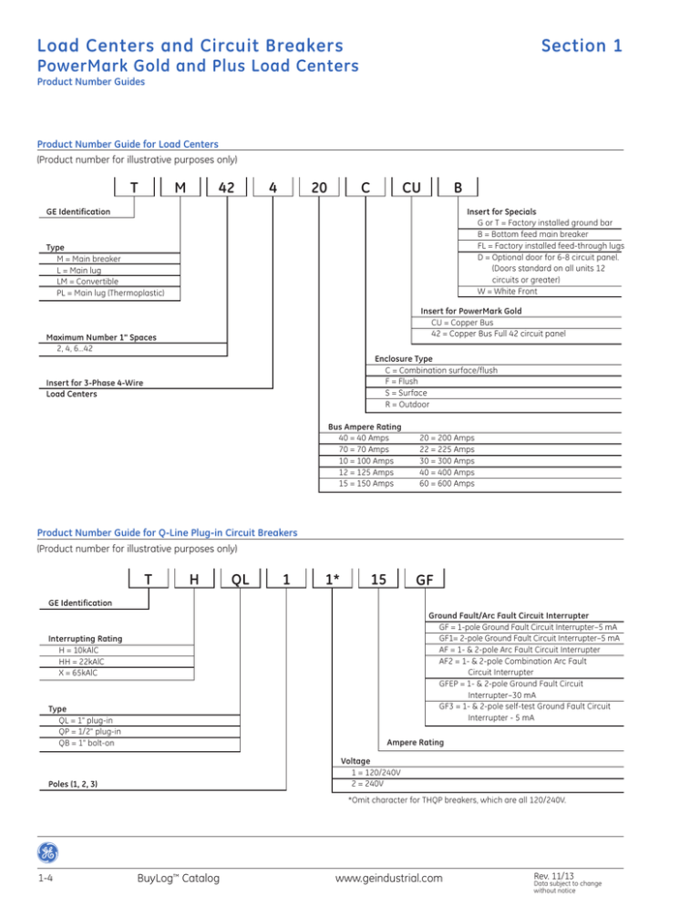
Load Centers and Circuit Breakers Section 1 PowerMark Gold and Plus Load Centers Product Number Guides Product Number Guide for Load Centers (Product number for illustrative purposes only) T M 42 4 20 C CU B Insert for Specials G or T = Factory installed ground bar B = Bottom feed main breaker FL = Factory installed feed-through lugs D = Optional door for 6-8 circuit panel. (Doors standard on all units 12 circuits or greater) W = White Front GE Identification Type M = Main breaker L = Main lug LM = Convertible PL = Main lug (Thermoplastic) Insert for PowerMark Gold CU = Copper Bus 42 = Copper Bus Full 42 circuit panel Maximum Number 1" Spaces 2, 4, 6…42 Enclosure Type C = Combination surface/flush F = Flush S = Surface R = Outdoor Insert for 3-Phase 4-Wire Load Centers Bus Ampere Rating 40 = 40 Amps 70 = 70 Amps 10 = 100 Amps 12 = 125 Amps 15 = 150 Amps 20 = 200 Amps 22 = 225 Amps 30 = 300 Amps 40 = 400 Amps 60 = 600 Amps Product Number Guide for Q-Line Plug-in Circuit Breakers (Product number for illustrative purposes only) T H QL 1 1* 15 GF GE Identification Ground Fault/Arc Fault Circuit Interrupter GF = 1-pole Ground Fault Circuit Interrupter–5 mA GF1= 2-pole Ground Fault Circuit Interrupter–5 mA AF = 1- & 2-pole Arc Fault Circuit Interrupter AF2 = 1- & 2-pole Combination Arc Fault Circuit Interrupter GFEP = 1- & 2-pole Ground Fault Circuit Interrupter–30 mA GF3 = 1- & 2-pole self-test Ground Fault Circuit Interrupter - 5 mA Interrupting Rating H = 10kAlC HH = 22kAlC X = 65kAlC Type QL = 1" plug-in QP = 1/2" plug-in QB = 1" bolt-on Ampere Rating Voltage 1 = 120/240V 2 = 240V Poles (1, 2, 3) *Omit character for THQP breakers, which are all 120/240V. 1-4 BuyLog™ Catalog www.geindustrial.com Rev. 11/13 Data subject to change without notice Load Centers and Circuit Breakers Section 1 PowerMark Gold and Plus Main Breaker Load Centers Load Center 1PH Main Breaker Indoor NEMA 1 Single-Phase, Three-Wire, 120/240 Vac Main Breaker Factory Installed Product Features —UL Listed (Panelboards No. 67) —60°C/75°C Conductor Rating —Suitable for Use as Service Entrance Equipment when Installed in Accordance with the National Electrical Code —22kAIC RMS symmetrical, Except Where Noted —6-42 circuit devices UL Listed for bottom mounted lugs by installing complete unit (box, interior and front) upside down. —For a listing of CSA Listed load centers, visit geindustrial.com. TM2020CCU TM820RCUFL Indoor (NEMA 1) Enclosure Main 1 Pole, Ampere 1” Rating Spaces 2 Pole, 1” Spaces 1 Pole, 1/2” Spaces 2 Pole, 1/2” Spaces Total 1-pole Spaces 100 12 5 20 8 22 100 24 12 0 0 24 100 20 10 0 0 20 100 32 16 0 0 32 125 12 5 20 8 22 125 24 12 0 0 24 125 16 8 16 6 24 125 16 8 16 6 24 150 16 8 32 14 32 150 16 8 32 14 32 Front Type Feed Type Box Number Main Wire Size (AWG/kcmil) Cu-Al Equipment Ground Kit Product Number Combination Flush/Surface Front Combination Flush/Surface Front Combination Flush/Surface Front Combination Flush/Surface Front Combination Flush/Surface Front Combination Flush/Surface Front Combination Flush/Surface Front Combination Flush/Surface Front Combination Flush/Surface Front Combination Flush/Surface Front Top Bottom 18 4-1/0 Included1 TM1210CCU2 Top Bottom 7 1-2/0 TGK24, TGK32 and TLK20 (order separately) TM2410CCU Top Bottom 6 4-1/0 TGK24 (order separately) TM2010CCU Top Bottom 11 4-1/0 TGK32 (order separately) TM3210CCU Top Bottom 18 1-2/0 Included1 TM1212CCU2 Top Bottom 7 1-2/0 TGK24 (order separately) TM2412CCU Top Bottom 4 1-2/0 TGK12 (order separately) TGK24 (order separately) TM1612CCU Top Bottom 4 1-2/0 TGK24 installed Top Bottom 7 1-3/0 (Cu), 2/0-3/0 (Al) TGK24 (order separately) TGK32 (order separately) Top Bottom 7 1-3/0 (Cu), 2/0-3/0 (Al) TGK32 installed TM1612CCUG TM1615CCU TM1615CCUG This table continued on next page 1-12 BuyLog™ Catalog www.geindustrial.com Rev. 11/13 Data subject to change without notice Load Centers and Circuit Breakers Section 1 PowerMark Gold and Plus Load Centers Circuit Breakers MAIN Wiring Diagrams MAIN C Breaker Fill Breaker Symbol 1” THQL D 1/2” THQP D D C C C C C C C MAIN 1 — 1 2 TL2440, TM2440 TM2010CCU, TM2010RCU Wire Range (AWG/kcmil) Terminal Symbol Cu MAIN MAIN C o 14-8 12-8 • 14-4 12-4 A 6-2 6-2 B 14-1/0 12-1/0 C 6-2/0 6-2/0 D 1-300 2/0-300 E 1-300 1-300 F 6-1 6-1 G 6-3 6-3 E TM2020CCU, TM2020RCU TLM2020CCU, TLM2020RCU TM2410CCU, TM2412CCU TM2412RCU, TLM2412CCU, TLM2412RCU C C MAIN C E MAIN C E MAIN MAIN C C TM3215CCU, TM3215RCU TM3210CCU TLM2420C42, TM2415C42 E MAIN MAIN TM2415RCU, TLM2415RCU C Al E C E E C MAIN MAIN TM3220CCU, TM3220RCU, TLM3220CCU TM4020CCU, TM4020RCU TLM4020CCU, TLM4020RCU C TM4222RCU, TLM4222CCU TLM4222RCU, TM4222CCU E TM12410 MAIN MAIN MAIN C D D D C C C C C C C MAIN TL12412 Rev. 11/13 Data subject to change without notice TM3215C42, TLM3220C42, TM3220C42 www.geindustrial.com TL2460 BuyLog™ Catalog 1-31


