RWM - VP ELECTRONIQUE
advertisement

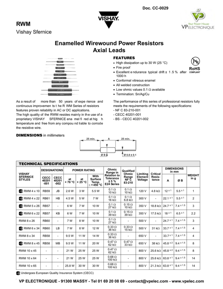
Doc. CC-0029 RWM Vishay Sfernice Enamelled Wirewound Power Resistors Axial Leads FEATURES • High dissipation up to 30 W (25 °C) • Fire proof • Excellent e ndurance typical drift ± 1 .5 % after 1000 h • Conformal vitreous enamel • All welded construction • Low ohmic values 0.1 Ω available • Termination: Sn/Ag/Cu 25 min. COMPLIANT The performance of this series of professional resistors fully meets the requirements of the following specifications: - NF C 83-210-001 - CECC 40201-001 - BS - CECC 40201-002 As a result of more than 50 years of expe rience and continuous improvemen ts t he R WM Series of resistors features proven reliability in AC or DC applications. The high quality of the RWM resides mainly in th e use of a proprietary VISHAY SFERNICE ena mel fi red at hig h temperature and free from any compou nd liable to corrode the resistive wire. DIMENSIONS in millimeters RoHS A ØB 25 min. Ø 0.8 ± 0.1 TECHNICAL SPECIFICATIONS VISHAY SFERNICE STYLES Ohmic Qualified Range in Ohmic Limiting Critical Relation to With Range Element ResisCECC Tolerance at at Surface NF C Voltage tance 40201 ± 5 % Temp. 83-210 -002 + 70 °C + 25 °C E24 Series ≤ + 450 °C DESIGNATIONS CECC 40201 -001 POWER RATING DIMENSIONS in mm A ØB WEIGHT in g RWM 4 x 10 RB59 JB 2.6 W 3W 5.5 W 0.1 Ω 10 kΩ 0.1 Ω 10 kΩ 120 V 4.8 kΩ 12 ± 1 5.5 ± 1 1 RWM 4 x 22 RB61 HB 4.5 W 5W 7W 0.1 Ω 16 kΩ 0.1 Ω 6.8 kΩ 300 V - 22.1 ± 1 5.5 ± 1 2 RWM 5 x 26 RB57 - 6W 7W 10 W 0.1 Ω 27 kΩ 0.15 Ω 10 kΩ 350 V 18.8 kΩ 24.7 ± 1 7.4 ± 1.5 3 RWM 6 x 22 RB57 KB 6W 7W 10 W 0.1 Ω 39 kΩ 0.15 Ω 39 kΩ 350 V 17.5 kΩ 18 ± 1 2.2 RB60 - 7W 8W 10 W 0.1 Ω 27 kΩ - 500 V - 24.7 ± 1 7.4 ± 1.5 3 RB60 LB 7W 8W 12 W 0.33 Ω 36 kΩ 0.33 Ω 15 kΩ 500 V 31 kΩ 33.7 ± 1 7.4 ± 1.5 4 RB58 - 9.5 W 11 W 14 W 0.33 Ω 36 kΩ - 650 V - 33.7 ± 1 7.4 ± 1.5 4 RB58 MB 9.5 W 11 W 20 W 0.47 Ω 62 kΩ 0.47 Ω 33 kΩ 650 V 38 kΩ 45.8 ± 2 9.4 ± 1.5 8 RWM 10 x 45 - - 21 W 25 W 25 W 0.47 Ω 62 kΩ - 800 V 25.6 kΩ 45.8 ± 2 9.4 ± 1.5 8 RWM 10 x 64 - - 21 W 25 W 25 W 0.68 Ω 100 kΩ - 800 V 25.6 kΩ 63.8 ± 1 9.4 ± 1.5 14 RWM 10 x 65 - - 25.8 W 30 W 30 W 0.68 Ω 100 kΩ - 800 V 21.3 kΩ 63.8 ± 1 9.4 ± 1.5 14 RWM 8 x 26 RWM 6 x 34 RWM 8 x 34 RWM 8 x 45 6.5 ± 1 Undergoes European Quality Insurance System (CECC) VP ELECTRONIQUE - 91300 MASSY - Tel 01 69 20 08 69 - contact@vpelec.com - www.vpelec.com Document Number: 50008 38 Revision: 11-Jun-08 Doc. CC-0029 RWM Enamelled Wirewound Power Resistors Axial Leads Vishay Sfernice PERFORMANCE CECC 40201 - EN 140-201 TESTS TYPICAL DRIFTS CONDITIONS REQUIREMENTS Short Time Overload 10 Pr during 10 s 25 °C ambient ± (2 % + 0.1 Ω) ± (0.5 % + 0.05 Ω) Temperature Cycling - 55 °C + 200 °C ± (1 % + 0.05 Ω) ± (0.5 % + 0.05 Ω) 56 days 40 °C Ambient - R.H. 95 % ± (5 % + 0.1 Ω) ± (0.5 % + 0.05 Ω) Tensile test: 20 N 2 successive bending 2 full rotations of 180° ± (1 % + 0.05 Ω) ± (0.1 % + 0.05 Ω) 1000 h at Pr 90/30 cycle 25 °C ambient ± (5 % + 0.1 Ω) ± (1.5 % + 0.05 Ω) Humidity (Steady State) Terminal Strength Load Life OVERLOAD Heavy overloads can be endured in the form of short pulses < 0.1 s. Parti cular requi rements should be submitted to Vishay Sfernice, sp ecifying p eak vol tage, cycl e and environmental conditions. RECOMMENDATIONS FOR USE Since the se components a re h igh d issipation power resistors, customers are advised to use a high melting point solder. Group Mounting In a still atmosphere, a distance between axes equal to five times the resistor’s diameter is recommended. Cabinet Mounting • Unven tilated box: dissip ation should b e redu ced (see dimensional drawing). • Forced ventilation: if conditions are appropriate, dissipation may be doubled or even trebled. • In an y case : the surface te mperature at th e hotte st po int should not exceed 450 °C. These aspects should be considered by the end user. For low oh mic va lues, the m easurement become s critical and the co nnecting wires resistance is to be included. The value is measured at 5 mm from the resistor body. ELECTRICAL SPECIFICATIONS Tolerance Stan dard On request ±5% ± 1 % and ± 2 % Temperature Coefficient + 75 ppm/°C typical Dielectric Withstanding Voltage NF EN 140000 Inductance 500 VRMS - 1 min - 10 mA non inductive (Ayrton-Perry) winding available VP ELECTRONIQUE - 91300 MASSY - Tel 01 69 20 08 69 - contact@vpelec.com - www.vpelec.com www.vishay.com Doc. CC-0029 RWM Enamelled Wirewound Power Resistors Axial Leads Vishay Sfernice TYPICAL TEMPERATURE RISE 75 50 25 0 0 25 100 200 300 34 34 x 6x 8 x 45 10 x4 5 10 4 x6 8 4x 10 5x 400 HOT SPOT TEMPERATURE IN °C % RATED POWER 100 4x 10 116 22 26 -6 x2 2 8x 26 POWER RATING CHART 5 x6 300 200 Optional 100 0 350 0 2 4 6 8 10 12 14 16 18 20 22 24 26 28 30 RATED POWER IN WATTS AMBIENT TEMPERATURE IN °C MARKING Sfernice trademark, model and style, CECC style, if applicable (except for the sma llest model due to lack of space : (4 x 10 or RB 59), ohmic value, resistance tolerance, manufacturing date (year - month). ORDERING INFORMATION RWM 4 x 10 MODEL STYLE XXX 1U2 ±5% AM500 e1 NI OPTIONAL SPECIAL DESIGN OHMIC VALUE TOLERANCE PACKAGING LEAD (Pb)-FREE Non Inductive Winding Method N° Optional Custom items are subject to extra charge and min. order. Please see price list. GLOBAL PART NUMBER INFORMATION R W GLOBAL MODEL RWM M 0 4 1 0 1 R 2 0 J R 1 5 E LEAD (Pb)-FREE SIZE OPTION OHMIC VALUE TOLERANCE PACKAGING SPECIAL d x L: 0410 0422 0526 0826 0634 0845 1045 1064 1065 Blank The firts three digits are significant fig ures and the last digit specifies the number of zeros to follow. R designates decimal point. F = 1% G=2% J=5% K = 10 % Size 0410, 0422, 0526, 0826, 0622: R15 = Reel (1000 pieces) As applicable Ex: AD7 or N (Non inductive winding) 48R7 = 48.7 Ω 1R20 = 1.2 Ω 1002 = 10 000 Ω R330 = 0.33 Ω ... 1 Sn(99), Ag(0.3), Cu(0.7): E1 Size 0845, 1045, 1064, 1065: B25 = Box (50 pieces) Size 0634: S09 = Bag (50 pieces) Other packaging existing VP ELECTRONIQUE - 91300 MASSY - Tel 01 69 20 08 69 - contact@vpelec.com - www.vpelec.com


