IR 1 2 3 4 5 6 7 8 9 10 11 12 13 T 14 15 16
advertisement
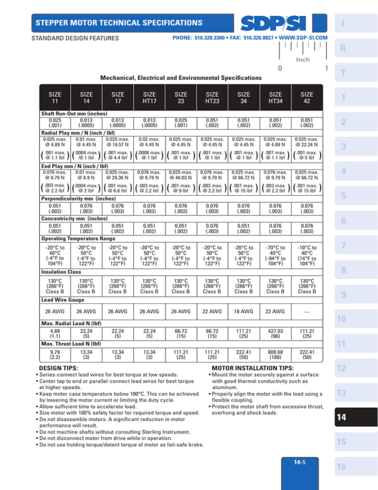
I STEPPER MOTOR TECHNICAL SPECIFICATIONS STANDARD DESIGN FEATURES PHONE: 516.328.3300 • FAX: 516.326.8827 • WWW.SDP-SI.COM R Inch 0 1 Mechanical, Electrical and Environmental Specifications SIZE 11 SIZE 17 SIZE HT17 SIZE 23 SIZE HT23 SIZE 34 SIZE HT34 SIZE 42 1 Shaft Run-Out mm (inches) 0.025 0.013 0.013 (.001) (.0005) (.0005) Radial Play mm / N (inch / lbf) 0.013 (.0005) 0.025 (.001) 0.051 (.002) 0.051 (.002) 0.051 (.002) 0.051 (.002) 2 0.02 max. @ 4.45 N 0.025 max. @ 4.45 N 0.025 max. @ 4.45 N 0.025 max. @ 4.45 N 0.025 max. @ 4.89 N 0.025 max. @ 22.24 N 0.025 max. @ 4.89 N SIZE 14 T 0.01 max. @ 4.45 N 0.025 max. @ 19.57 N max. .0004 max. .0008 max. .001 max. .001 max. .001 max. .001 max. .001 max. .001 max. ( .001 @ 1.1 lbf ) ( @ 1 lbf ) ( @ 4.4 lbf ) ( @ 1 lbf ) ( @ 1 lbf ) ( @ 1 lbf ) ( @ 1 lbf ) ( @ 1.1 lbf ) ( @ 5 lbf ) End Play mm / N (inch / lbf) 0.076 max. @ 9.79 N 0.01 max. @ 8.9 N 0.025 max. @ 29.36 N 0.076 max. @ 9.79 N 0.025 max. @ 40.03 N 0.076 max. @ 9.79 N 0.025 max. @ 66.72 N 0.076 max. @ 9.79 N 0.025 max. @ 66.72 N max. .0004 max. .001 max. .003 max. .001 max. .003 max. .001 max. .003 max. .001 max. ( .003 @ 2.2 lbf ) ( @ 2 lbf ) ( @ 6.6 lbf ) ( @ 2.2 lbf ) ( @ 9 lbf ) ( @ 2.2 lbf ) ( @ 15 lbf ) ( @ 2.2 lbf ) ( @ 15 lbf ) Perpendicularity mm (inches) 0.051 0.076 0.076 (.002) (.003) (.003) Concentricity mm (inches) 0.051 0.051 0.051 (.002) (.002) (.002) Operating Temperature Range -20°C to 40°C (-4°F to 104°F) -20°C to 50°C (-4°F to 122°F) 0.076 (.003) 0.076 (.003) 0.076 (.003) 0.076 (.003) 0.076 (.003) 0.076 (.003) 0.051 (.002) 0.051 (.002) 0.076 (.003) 0.051 (.002) 0.076 (.003) 0.076 (.003) -20°C to 50°C (-4°F to 122°F) -20°C to 50°C (-4°F to 122°F) -20°C to 50°C (-4°F to 122°F) -20°C to 50°C (-4°F to 122°F) -20°C to 50°C (-4°F to 122°F) -70°C to 40°C (-94°F to 104°F) -10°C to 40°C (14°F to 104°F) 130°C (266°F) Class B 130°C (266°F) Class B 130°C (266°F) Class B 130°C (266°F) Class B 130°C (266°F) Class B 130°C (266°F) Class B 130°C (266°F) Class B 26 AWG 26 AWG 26 AWG 22 AWG 18 AWG 22 AWG — 22.24 (5) 22.24 (5) 66.72 (15) 66.72 (15) 111.21 (25) 427.03 (96) 111.21 (25) 13.34 (3) 13.34 (3) 111.21 (25) 111.21 (25) 222.41 (50) 800.68 (180) 222.41 (50) Insulation Class 130°C (266°F) Class B 130°C (266°F) Class B Lead Wire Gauge 26 AWG 26 AWG Max. Radial Load N (lbf) 4.89 22.24 (1.1) (5) Max. Thrust Load N (lbf) 9.79 (2.2) DESIGN TIPS: 13.34 (3) MOTOR INSTALLATION TIPS: • Series-connect lead wires for best torque at low speeds. • Mount the motor securely against a surface • Center tap to end or parallel-connect lead wires for best torque with good thermal conductivity such as at higher speeds. aluminum. • Keep motor case temperature below 100°C. This can be achieved • Properly align the motor with the load using a by lowering the motor current or limiting the duty cycle. flexible coupling. • Allow sufficient time to accelerate load. • Protect the motor shaft from excessive thrust, • Size motor with 100% safety factor for required torque and speed. overhung and shock loads. • Do not disassemble motors. A significant reduction in motor performance will result. • Do not machine shafts without consulting Sterling Instrument. • Do not disconnect motor from drive while in operation. • Do not use holding torque/detent torque of motor as fail-safe brake. 14-5 3 4 5 6 7 8 9 10 11 12 13 14 15 16
