2ee 01 basic electrical engineering
advertisement
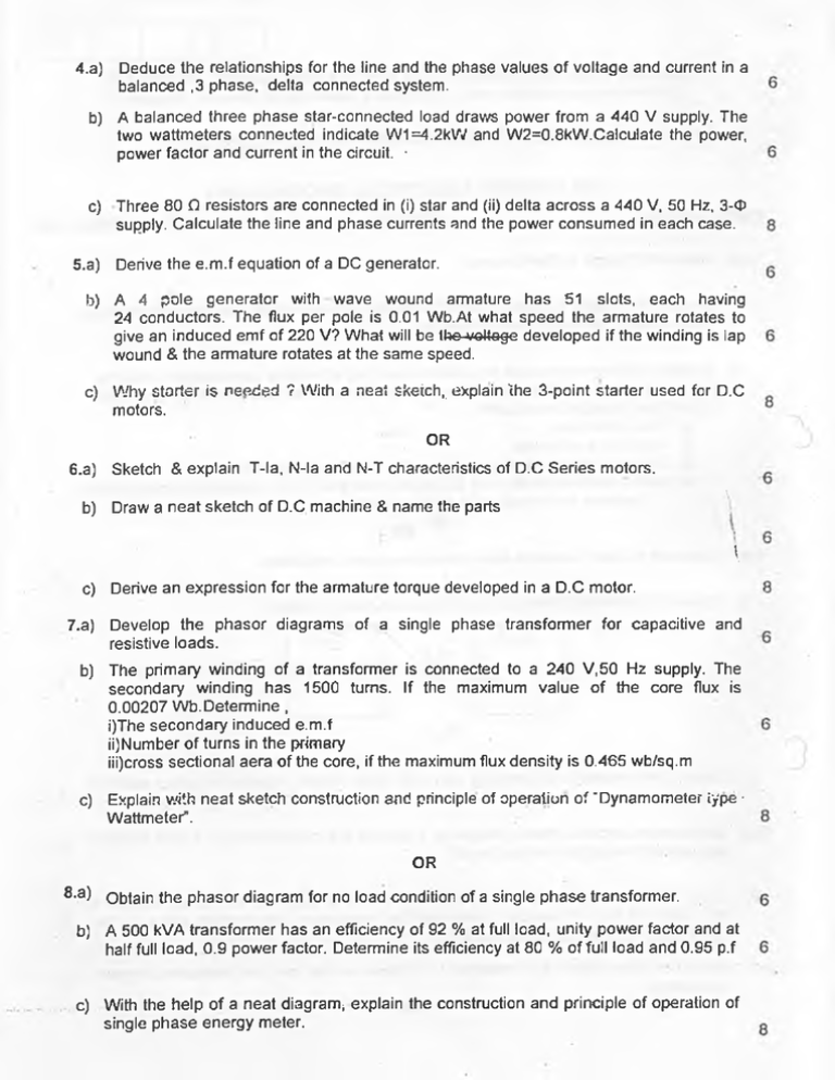
4.a) Deduce the relationships for the line and the phase values of voltage and current in a balanced ,3 phase, delta connected system. b) A balanced three phase star-connected load draws power from a 440 V supply. The two wattmeters connected indicate W1=4.2kW and W2=0.8kW.Calculate the power, power factor and current in the circuit. • c) Three 80 Q resistors are connected in (i) star and (ii) delta across a 440 V, 50 Hz, 3-<P supply. Calculate the line and phase currents and the power consumed in each case. 5.a) Derive the e.m.f equation of a DC generator. b) A 4 pole generator with wave wound armature has 51 slots, each having 24 conductors. The flux per pole is 0.01 Wb.At what speed the armature rotates to give an induced emf of 220 V? What will be the voUa$e developed if the winding is lap wound & the armature rotates at the same speed. c) Why starter is needed ? With a neat Sketch,, explain the 3-point starter used for D.C motors. OR 6.a) Sketch & explain T-la, N-la and N-T characteristics of D.C Series motors. . ,\ b) Draw a neat sketch of D.C machine & name the parts \ c) Derive an expression for the armature torque developed in a D.C motor. 7.a) Develop the phasor diagrams of a single phase transformer for capacitive and resistive loads. b) The primary winding of a transformer is connected to a 240 V.50 Hz supply. The secondary winding has 1500 turns. If the maximum value of the core flux is 0.00207 Wb.Determine, i)The secondary induced e.m.f ii)Number of turns in the primary iii)cross sectional aera of the core, if the maximum flux density is 0.465 wb/sq.m c) Explain with neat sketch construction and principle of operation of “Dynamometer iype • Wattmeter". OR 8.a) Obtain the phasor diagram for no load condition of a single phase transformer. b) A 500 kVA transformer has an efficiency of 92 % at full load, unity power factor and at half full load, 0.9 power factor. Determine its efficiency at 80 % of full load and 0.95 p.f c.) With the help of a neat diagram* explain the construction and principle of operation of single phase energy meter. 9.a) With necessary sketches distinguish between, salient pole and cylindrical pole type synchronous generators and when these are preferred. b) A 6-pole, three phase, star connected alternator has an armature with 90 slots and 8 conductors per slot & rotates at 1000 r.p.m.The flux per pole is 0.05 Wb. Calculate the phase & line values of e.m.f generated ,if the winding factor is 0.97 & pitch factor is unity. c) Show that the Rotating Magnetic field (R.M.F) produced by a 3 - <P induction motor, when it is connected to 3-0 supply, is of constant magnitude and rotates at synchronous speed. 0 6 ■.• 8 OR 10.a) A 3-<J> induction motor has 6-poles and runs at 960 r.p.m on full load. It is supplied from an alternator, having 4 poles and running at 1500 r.p.m. Calculate the full load slip and the frequency of the rotor current of the induction motor. 6 b) Define slip. Derive an expression for the slip and frequency of rotor current of a 3-phase induction motor. 6 c) A three phase, 16 pole alternator has a star connected winding with 144 slots and 10 conductors per slot. The flux per pole is 0.03 Wb and the speed is 375 r.p.m. Find the frequency and the phase & the line electro motive force. Given,Kd=0.96 & Kc=1 Q Common for sections F,G,H,I & J *\ V 0 V * * -' ' Vs/ <V SRI SIDDHARTHA INSTITUTE OF TECHNOLOGY, TUMKUR. (An Autonomous Institution under Visvesvaraya Technological University, Belgaum.) * B.E., SEMESTER END EXAMINATIONS - JUNE 2011 EE 01 :BASIC ELECTRICAL ENGINEERING TIME: 3.00 Hrs SEM: II MAX MARKS: 100 1.a) State and Explain Kirchoffs laws. .6 b) Mention the different types of wiring? With the relevant circuit diagram and switching table, explain three-way control of lamps. q c) A coil of 1000 turns is wound on a silicon steel ring of relative permeability 1200.The ring has mean diameter of 10 cm & cross sectional area of 12 sq.cm.When a current of 4 A flows through the coil,find i) Flux in the core ii) Inductance of the coil iii) The e.m.f induced in the coil ,if the flux falls to zero in 15 m.sec iv) Now,if another similar coil is placed such that 70% magnetic coupling exists between the coils,find the mutual inductance. OR 2.a) State and explain Faraday’s laws of electromagnetic induction, b) Obtain the potential difference Vxy in the circuit given in figure. 1 . C) Explain the necessity of earthing and with neat sketch explain the plate earthing method. p 3.a) With relevant circuit & phasor diagrams, show that the current through a pure inductor lags behind the applied voltage by 90°. 0 b) A non inductive resistor of 10 O is in series with a capacitor of 100 pF across a 250 volts, 50 Hz, AC supply. Determine the impedance, the current taken by the capacitor and power factor of the circuit. 6 -c).- Show .that the power in a balanced 3. phase, circuit can be measured by two • 8 wattmeters. OR
