Conversion of the 2.5MV Super HILAC Injector Power Supply from
advertisement

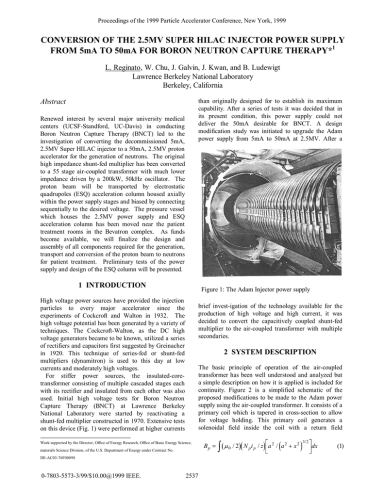
Proceedings of the 1999 Particle Accelerator Conference, New York, 1999 CONVERSION OF THE 2.5MV SUPER HILAC INJECTOR POWER SUPPLY FROM 5mA TO 50mA FOR BORON NEUTRON CAPTURE THERAPY*1 L. Reginato, W. Chu, J. Galvin, J. Kwan, and B. Ludewigt Lawrence Berkeley National Laboratory Berkeley, California than originally designed for to establish its maximum capability. After a series of tests it was decided that in its present condition, this power supply could not deliver the 50mA desirable for BNCT. A design modification study was initiated to upgrade the Adam power supply from 5mA to 50mA at 2.5MV. After a Abstract Renewed interest by several major university medical centers (UCSF-Standford, UC-Davis) in conducting Boron Neutron Capture Therapy (BNCT) led to the investigation of converting the decommissioned 5mA, 2.5MV Super HILAC injector to a 50mA, 2.5MV proton accelerator for the generation of neutrons. The original high impedance shunt-fed multiplier has been converted to a 55 stage air-coupled transformer with much lower impedance driven by a 200kW, 50kHz oscillator. The proton beam will be transported by electrostatic quadrupoles (ESQ) acceleration column housed axially within the power supply stages and biased by connecting sequentially to the desired voltage. The pressure vessel which houses the 2.5MV power supply and ESQ acceleration column has been moved near the patient treatment rooms in the Bevatron complex. As funds become available, we will finalize the design and assembly of all components required for the generation, transport and conversion of the proton beam to neutrons for patient treatment. Preliminary tests of the power supply and design of the ESQ column will be presented. 1 INTRODUCTION Figure 1: The Adam Injector power supply High voltage power sources have provided the injection particles to every major accelerator since the experiments of Cockcroft and Walton in 1932. The high voltage potential has been generated by a variety of techniques. The Cockcroft-Walton, as the DC high voltage generators became to be known, utilized a series of rectifiers and capacitors first suggested by Greinacher in 1920. This technique of series-fed or shunt-fed multipliers (dynamitron) is used to this day at low currents and moderately high voltages. For stiffer power sources, the insulated-coretransformer consisting of multiple cascaded stages each with its rectifier and insulated from each other was also used. Initial high voltage tests for Boron Neutron Capture Therapy (BNCT) at Lawrence Berkeley National Laboratory were started by reactivating a shunt-fed multiplier constructed in 1970. Extensive tests on this device (Fig. 1) were performed at higher currents brief invest-igation of the technology available for the production of high voltage and high current, it was decided to convert the capacitively coupled shunt-fed multiplier to the air-coupled transformer with multiple secondaries. 2 SYSTEM DESCRIPTION The basic principle of operation of the air-coupled transformer has been well understood and analyzed but a simple description on how it is applied is included for continuity. Figure 2 is a simplified schematic of the proposed modifications to be made to the Adam power supply using the air-coupled transformer. It consists of a primary coil which is tapered in cross-section to allow for voltage holding. This primary coil generates a solenoidal field inside the coil with a return field Work supported by the Director, Office of Energy Research, Office of Basic Energy Science, materials Science Division, of the U.S. Department of Energy under Contract No. DE-AC03-76F00098 0-7803-5573-3/99/$10.00@1999 IEEE. 2537 Bp 0 / 2 N p i p / z a 2 / a 2 x 2 3/ 2 dx (1) Proceedings of the 1999 Particle Accelerator Conference, New York, 1999 between the pressure vessel and the coil itself. The flux density within the solenoidal coil can be obtained by summing the contributions of each turn of the coil. This results in a flux density. Where: Np – number of primary turns, a–radius of the solenoid, z-length of the solenoid and dx is an element of length. At points within the solenoid not too close to either end, the flux density produced can be approximated by Bp=0Npip/z. Within the primary coil, 55 stages of multi-turn secondary coils are located. The flux generated by the primary (Bp) is coupled by magnetic induction to each secondary generating a voltage Vs=NsAsdBp/dt where As is the cross-sectional area and Ns the number of secondary turns. Each secondary coil incorporates a rectifier and filter producing a self-contained power source. Each power source is series connected to the next producing a high voltage system. The coupled transformer system, like the shunt-fed multiplier, has an impedance which increases linearly with the number of stages and is a function of the coupling coefficient between the primary and secondary coil. The primary coil will be part of the main oscillator resonant circuit with an inductance Lp0Np2Ap/z. This inductance will resonate with a capacitor Cp=1/w2Lp. The secondary voltage induced will be Vs=NsAswBp and Bp=oNpip/z where ip=Vp/wLp. By substitution Vs=(Ns/Np)(As/Ap)Vp. The subscripts s and p refer to the secondary and primary respectively. Prior to modifying the Adam power supply, an eight stage coupled transformer bench top model was constructed and tested. A conducting cover was placed around it to simulate the pressure vessel. The test results were encouraging in that it confirmed our calculations and had an order of magnitude lower impedance than the shunt-fed device. dome (Fig. 3). The number of turns per unit of length or Figure 3: The air-coupled transformer primary pitch of the coil also increases linearly from the ground end to the high voltage dome in order to maintain a constant flux density or constant induced voltage into Figure 5: One of 55 series stages 3 SYSTEM MODIFICATION The coupling capacitors, the dees and the oscillator coil of the shunt-fed multiplier were removed. The dees were replaced by the primary. solenoidal coil with an increasing inside diameter toward the high voltage the secondary coils. The number of turns was further increased at each end of the coil to correct for end effects of the dome and the ground. Figure 4 shows a plot of the induced voltage in the secondary coil along Figure 2: The air-coupled transformer modifications to the power supply 2538 Proceedings of the 1999 Particle Accelerator Conference, New York, 1999 the length of the power supply where the acceleration column would be located. As can be seen, except for the ends, the induced voltage in each of the 55 secondary coils will be quite uniform. The secondary coils will begin about 12” from the end wall and will terminate about 18” from the dome to insure that the coupled voltage for the end stages is constant. HV Dome 1.0 0.8 0.6 Bz 4 SYSTEM OPERATION 0.4 The master oscillator consisting of a 4 CW100,000 drives the primary coil with 50kHz at 50-75kV. The oscillator is powered by a 15kV, 12.5A regulated DC power supply and with a projected efficiency of 67% it will deliver 125kW to the beam or 2.5MV at 50mA. A closed loop feedback system will maintain the desired acceleration voltage on the electrostatic quadrupoles (ESQ) at any beam current. The flux density generated by the primary coil couples to the 100 turn secondary inducing about 50 kV in each of the 55 stages which are series connected. The 50 kHz signal is rectified by the shielded diodes and filtered by a 10k resistor and a 1nF capacitor. The diode shields and series resistor protect the diodes if an arcdown condition occurs. The beam transport system will consist of electrostatic quadrupoles (ESQ) which have undergone considerable development in the LBNL neutral beam and heavy ion fusion programs. The protons are produced by a rf driven gas source which was also developed in the neutral beam program. 0.2 Z (in) 20 40 60 80 100 120 140 Figure 4: Flux density or coupled secondary voltage from 5mA to 50mA for BNCT at a relatively low cost since many of the major existing components were reutilized. All the components for the power supply are on hand and as funds become available the complete system including ESQ’s and beam transport will be designed and fabricated. The injector is located adjacent to the patient treatment rooms (Fig. 6) in Bldg. 51B. 6 REFERENCES [1]B.A. Ludewigt, “An Epithermal Neutron Source for BNCT”, Proc. Of Topical Meeting on Nuclear Appl., of Accel., Technology, Albuguerque, NM, (1997) [2]J.W. Kwan, “Applications of Accelerators in Science and Industry”, AIP Conference Proceedings, (1998) 5 CONCLUSION [3]M.R. Clevland, IEEE, “Transactions on Nuclear Science”, (1965), Vol. NS12 The air-coupled transformer with multiple secondaries provided the ideal upgrade to an existing power supply Figure 6: Injector adjacent to patient treatment rooms 2539


