550582 - MTS Sensors
advertisement

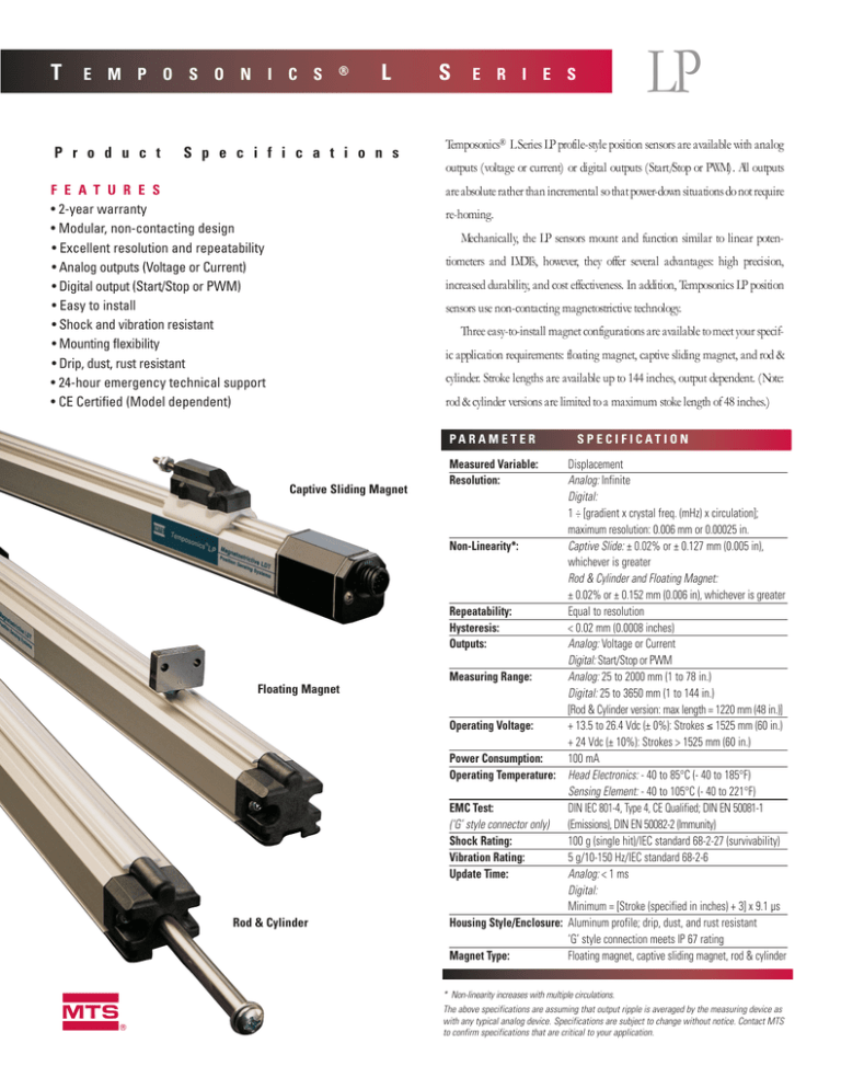
T E M P O S O N I C S P r o d u c t ® L S p e c i f i c a t i o n s S LP E R I E S Temposonics® L Series LP profile-style position sensors are available with analog outputs (voltage or current) or digital outputs (Start/Stop or PWM). All outputs F E A T U R E S • 2-year warranty • Modular, non-contacting design • Excellent resolution and repeatability • Analog outputs (Voltage or Current) • Digital output (Start/Stop or PWM) • Easy to install • Shock and vibration resistant • Mounting flexibility • Drip, dust, rust resistant • 24-hour emergency technical support • CE Certified (Model dependent) are absolute rather than incremental so that power-down situations do not require re-homing. Mechanically, the LP sensors mount and function similar to linear potentiometers and LVDTs, however, they offer several advantages: high precision, increased durability, and cost effectiveness. In addition, Temposonics LP position sensors use non-contacting magnetostrictive technology. Three easy-to-install magnet configurations are available to meet your specific application requirements: floating magnet, captive sliding magnet, and rod & cylinder. Stroke lengths are available up to 144 inches, output dependent. (Note: rod & cylinder versions are limited to a maximum stoke length of 48 inches.) PARAMETER Captive Sliding Magnet Floating Magnet Rod & Cylinder m S P E C I F I C AT I O N Measured Variable: Resolution: Displacement Analog: Infinite Digital: 1 ÷ [gradient x crystal freq. (mHz) x circulation]; maximum resolution: 0.006 mm or 0.00025 in. Non-Linearity*: Captive Slide: ± 0.02% or ± 0.127 mm (0.005 in), whichever is greater Rod & Cylinder and Floating Magnet: ± 0.02% or ± 0.152 mm (0.006 in), whichever is greater Repeatability: Equal to resolution Hysteresis: < 0.02 mm (0.0008 inches) Outputs: Analog: Voltage or Current Digital: Start/Stop or PWM Measuring Range: Analog: 25 to 2000 mm (1 to 78 in.) Digital: 25 to 3650 mm (1 to 144 in.) [Rod & Cylinder version: max length = 1220 mm (48 in.)] Operating Voltage: + 13.5 to 26.4 Vdc (± 0%): Strokes ≤ 1525 mm (60 in.) + 24 Vdc (± 10%): Strokes > 1525 mm (60 in.) Power Consumption: 100 mA Operating Temperature: Head Electronics: - 40 to 85°C (- 40 to 185°F) Sensing Element: - 40 to 105°C (- 40 to 221°F) DIN IEC 801-4, Type 4, CE Qualified; DIN EN 50081-1 EMC Test: (‘G’ style connector only) (Emissions), DIN EN 50082-2 (Immunity) Shock Rating: 100 g (single hit)/IEC standard 68-2-27 (survivability) Vibration Rating: 5 g/10-150 Hz/IEC standard 68-2-6 Update Time: Analog: < 1 ms Digital: Minimum = [Stroke (specified in inches) + 3] x 9.1 µs Housing Style/Enclosure: Aluminum profile; drip, dust, and rust resistant ‘G’ style connection meets IP 67 rating Magnet Type: Floating magnet, captive sliding magnet, rod & cylinder * Non-linearity increases with multiple circulations. The above specifications are assuming that output ripple is averaged by the measuring device as with any typical analog device. Specifications are subject to change without notice. Contact MTS to confirm specifications that are critical to your application. O U T P U T S A N A L O G & D I G I TA L O U T P U T S The Temposonics L Series LP position (PWM) outputs are also available. sensors provide direct analog or digital The Start/Stop output requires a cus- outputs. tomer-supplied 1µs interrogation Analog outputs include: voltage signal. (0 to 10 Vdc; forward & reverse acting) Since both the analog and digital and current (4 - 20 mA or 0 - 20 mA, outputs are direct, no signal-condi- forward or reverse acting). tioning electronics are needed when If a digital format is required, Start/Stop or Pulse-width Modulated interfacing with controllers or meters. F E AT U R E S • Outputs Include: - Start/Stop - Pulse-width modulated (PWM) • Rugged Construction • Direct Outputs—No Signalconditioning Required - Voltage • High Resolution - Current • Drip, Dust, Rust Resistant M A G N E T C O N F I G U R AT I O N S Floating Magnet CAUTION: When optimum LP sensor performance is required, use of a captive sliding magnet or rod & cylinder version is recommended since they provide the best magnetic coupling to the sensor’s waveguide. Use of a floating magnet (P/N 251298-2) requires strict adherence to tolerances to achieve specified sensor performance. Variations to tolerances will result in reduced performance. 2 D I M E N S I O N S M A G N E T C O N F I G U R AT I O N S Temposonics LP profile-style position sensors offer modular construction, flexi- Temposonics LP sensors are effective in applications where space is an issue ble mounting configurations, and easy installation. There are three magnet and in environments where there are dust and contamination. They are configurations offered to meet the mounting requirements of your application: designed for external mounting on machines and can be configured with a (1) floating magnet, (2) captive sliding magnet, and (3) rod and cylinder variety of connection options. (refer to the illustrations, below). Captive Sliding Magnet Rod & Cylinder NOTES: 1. Standard mounting feet shown. Low profile feet optional. Refer to P/N 400802 or P/N 400867 on the accessory page for detailed dimensional information. 2. Proper mounting and alignment of sensor is critical to ensure normal operation. Optional LP Rod End Enlarged profile view CONNECTOR DIMENSIONS (includes cable bend) • ‘G’ Connector w/ Straight Exit ‘RG’ Mating Connector: 61 mm (2.4 in.) • ‘G’ Connector w/90° ‘RA’ Mating Connector: 34 mm (1.35 in.) • ‘C’ Integral Connector w/Mating Connector: 114.3 mm (4.5 in.) • ‘H’, ‘J’, ‘L’, and ‘M’ Integral Cables: 20 mm (0.8 in.) 3 W I R I N G CONNECTIONS Analog Output: Vo l t a g e O u t p u t : Analog Output: Current Output: Digital Output: (PWM or Start/Stop) Pin No. 1 2 3 4 5 6 7 8 Pin No. Wire Color 1 Blue Pin No. 1 2 3 4 5 6 7 8 Wire Color Blue Green Yellow Orange Red Black Drain Wire N/C Function 0 to 10 Vdc (Note 1) Return for Pin 1 10 to 0 Vdc (Note 2) Return for Pin 3 Customer Supplied Power (+ Vdc)* DC Ground Shield Drain Wire (Note 3) N/C 2 3 4 5 6 7 8 Green Yellow Orange Red Black Drain Wire N/C Function 4 to 20 mA, 0 to 20 mA 20 to 4 mA, or 20 to 0 mA Return for Pin 1 N/C N/C Customer Supplied Power (+ Vdc)* DC Ground Shield Drain Wire (Note 3) N/C Wire Color Blue Green Yellow Orange Red Black Drain Wire N/C Function (PWM) (-) Gate for PWM, (-) Stop for Start/Stop (+) Gate for PWM, (+) Stop for Start/Stop (-) Interrogation for PWM, (-) Start for Start/Stop (+) Interrogation for PWM, (+) Start for Start/Stop Customer Supplied Power (+ Vdc)* DC Ground Shield Drain Wire (Note 3) N/C * Power requirements are stroke length dependent. + 13.5 to 26.4 Vdc (± 0%): Stroke lengths ≤ 1525 mm (60 in.) + 24 Vdc (± 10%): Stroke lengths > 1525 mm (60 in.) NOTES: 1. Output = 0 Vdc when reference magnet is positioned at the electronics housing end of the sensor. 8-Pin Integral or Hanging Connector (male profile) Connection Type ‘C’, ‘H’, or ‘J’ Mating Accessories: • P/N 251135 Field Installable Connector • Extension Cables 2. Output = 0 Vdc when reference magnet is positioned at the tip of the sensor. 3. Shield drain wire should be isolated from DC ground (black wire) at the controller end of the cable. C O N N E C T I O N S F O R ‘ G ’ S T Y L E M AT I N G C A B L E S RG Connector: (PWM or Start/Stop) RG Connector: (Voltage or Current Output) Pin No. 1 2 3 4 5 6 7 Pin No. Wire Color 1 Gray Wire Color Gray Pink Yellow Green Red or Brown White - Function (-) Gate for PWM, (-) Stop for Start/Stop (+) Gate for PWM, (+) Stop for Start/Stop (+) Interrogation for PWM, (+) Start for Start/Stop (-) Interrogation for PWM, (-) Start for Start/Stop Customer Supplied Power (+ Vdc)* DC Ground No Connection NOTES: 1. When wiring Temposonics L Series LP sensors equipped with a ‘G’ style connector, do not connect DC ground to the cable shield or drain wire. 2 3 4 5 6 7 Function 0 to 10 Vdc 4 to 20 mA or 0 to 20 mA Pink Return for Pin 1 Yellow 10 to 0 Vdc 20 to 4 mA or 20 to 0 mA Green Return for Pin 3 Red or Brown Customer Supplied Power (+ Vdc)* White DC Ground No Connection ‘G’ Connector (Molded Mating Extension Cable Required) * Power requirements are stroke length dependent. + 13.5 to 26.4 Vdc (± 0%): Stroke lengths ≤ 1525 mm (60 in.) + 24 Vdc (± 10%): Stroke lengths > 1525 mm (60 in.) 2.) For single-ended interrogation, the unused interrogation lead must be connected to DC ground. 3.) When using PWM with internal interrogation, both interrogation leads must be connected to DC ground. TYPICAL 4-20 mA WIRING: NOTE: Minimum load impedance for voltage outputs is 5K Ω. 4 H O W T O O R D E R Optional POSITION 0 0 SENSOR When placing an order, build the desired model number using the SENSOR MODEL LP = Profile Style Sensor (mounting feet included, Note 1) S= model number guide (right). A selection of Temposonics LP sensor configurations are available to meet D= M= R= the demands of your particular application. If you have any questions about how to apply MTS Temposonics C= G= L= M= H= J= position sensors, please contact one of our Application Engineers or your local distributor—they are available to help you design an effective position sensing system to fit your application. MAGNET CONFIGURATION Captive Sliding Magnet (Note 3) (provided with #10-32 threads when stroke length is defined in inches; provided with M5 threads when stroke length is defined in millimeters) Captive Sliding Magnet (for Die Cast) Additional rod end (P/N 560444) is required, order separately Consult Applications Engineering before ordering. Floating Magnet (P/N 251298-2, included with sensor) (Note 3) Rod & Cylinder (Note 3) CONNECTION TYPE Integral Connector (mating connector ordered separately) 7-pin Micro connector (CE approved) Cable (7 ft.) with pigtail connection Cable (7 ft.) with pigtail connection; configured for dual rod ends, kit included - P/N 251411 Cable (7 ft.) with attached connector Cable (7 ft.) with attached connector; configured for dual rod ends, kit included - P/N 251411 S= P= V= A= B= C= D= OUTPUT Start/Stop Pulse-width Modulated (See ‘PWM Output’ for options, below) Voltage (0 to +10 Vdc or +10 to 0 Vdc) 4 to 20 mA 20 to 4 mA 0 to 20 mA 20 to 0 mA U= M= UNIT OF MEASURE US customary (inches and tenths: xxx.x in.) Metric (millimeters: xxxx mm) LENGTH (see Notes 2 & 3) __ __ __ . __ = Inches and tenths (Encode length in 1.0 in. increments) or __ __ __ __ millimeters (Encode length in 5 mm increments) 1= 2= Stroke Length Limitations: Sensors with analog output: 78 in. (2000 mm). Sensors with digital output: 144 in. (3650 mm). Rod & Cylinder sensors: 48 in. (1225 mm). PWM OUTPUT Complete the following only if Output style ‘P’ is selected, above 0 0 __ __ __ = PWM Output (Fill in the three blanks with the following codes) a b c b, c) Circulations a) Interrogation E = External __ __ = desired number of circulations (see tables A and B) I = Internal Table B Table A Circulation Count vs. Resolution for PWM Output (Based on 28 MHz counter) Resolution INPUT VOLTAGE +13.5 to 26.4 Vdc (± 0%) for strokes ≤ 60 inches +24 Vdc (± 10%) for strokes > 60 inches Circulation Count* Maximum Stroke per Circulation Count for PWM Output w/Internal Interrogation Maximum Stroke Circulation Count 15 ≤ 84 inches 15 0.0005 8 > 84.1 inches 1 0.001 4 0.002 2 0.004 1 0.00026 * Maximum circulation count is limited by stroke length for sensors configured for internal interrogation. (Refer to Table B for stroke length limitations.) NOTES: 1. Standard mounting feet (P/N 400802) are included with Temposonics LP sensors with connection types C, L , or H (not provided with connection types M or J). 2. Standard Temposonics LP stroke lengths: 3, 6, 9, 12, 15, 18, 21, 24, 30, 36, 42, 48 inches. 3. Non-standard lengths are available in 1 inch increments up to 144 inches (analog units are limited to 78 inches) except for rod and cylinder versions which are limited to a maximum stroke length of 48 inches (1225 mm). Additional lead time may be required for non-standard lengths. 4. Standard extension cable lengths available. RETROFIT NOTE: Please consult an MTS applications engineer before retrofitting an original Temposonics LP that is being used with a Temposonics accessory product such as an AOM, TDU100, MK292, etc. 5 H O W T O EXTENSION O R D E R ( c o n t . ) CABLES C o n n e c t o r Ty p e s ‘ C ’ , ‘ H ’ , & ‘ J ’ M a t i n g E x t e n s i o n C a b l e s L 005 = 015 = 025 = XXX = CABLE LENGTH 5 ft. 15 ft. 25 ft. Custom length (range: 5 to 100 ft.) NOTE: Extension cables terminate with a pigtail connection. C o n n e c t o r Ty p e ‘ G ’ M a t i n g E x t e n s i o n C a b l e s SENSORS CONNECTION TYPE RG = Mating Connector for Style “G” sensor only (straight) RA = Mating Connector for Style “G” sensor only (90°) 005 = 015 = 025 = 050 = 100 = CABLE LENGTHS 5 ft. 15 ft. 25 ft. 50 ft. 100 ft. CABLE TERMINATION P0 = Pigtail connection NOTE: Extension cable terminates with a pigtail connection. 6 ACCESSORIES Description Part No. Notes LP Magnet Assembly (spare) 251298-2 Spare for Temposonics LP position sensors with floating magnet Mounting Screws (8/32 x 3/4 in. Stainless Steel) 560712 Spare for mounting floating magnet assembly, P/N 251298-2, for use with Magnet Configuration ‘M’. Captive Sliding Magnet, US version (spare) 252052 Spare for Temposonics LP position sensors with electrical strokes defined in inches (#10-32 threads). See drawing, below Captive Sliding Magnet, Metric version (spare) 252053 Spare for Temposonics LP position sensors with electrical strokes defined in millimeters (M5 threads). See drawing, below Power Supply (24/28 Vdc, 0.5 A) 380009 Mounting Feet, Standard (spare) 400802 See drawing, below Mounting Feet, Low Profile (optional) 400867 See drawing, below Rod End 560444 For use with Temposonics LP sensors with Connection Types ‘M’ or ‘J’ (rod & cylinder versions) to provide a means to attach the LP rod to customer equipment, See drawing, below Threaded Stud End Kit 251975 For use with Temposonics LP sensors (rod & cylinder versions) to provide a means to attach the LP rod to customer equipment. Includes threaded stud with stationary jamb nut, two (2) hex nuts and a washer. See drawing, below Field-Installable Receptacle Connector Kit 251135 Mating connector for Temposonics LP sensor with connection types ‘C’, ‘H’, or ‘J’. Mounting Feet Standard (P/N 400802) Threaded Rod End (P/N 560444) Captive Sliding Magnet (P/N 252052 & 252053) Low Profile (P/N 400867) Threaded Stud End (P/N 251975) Captive Sliding Magnet (P/N 252092) for die cast applications 7 m Pioneers, Innovators, Leaders in Magnetostrictive Sensing SENSORS G R O U P UNITED STATES GERMANY JAPAN MTS Systems Corporation Sensors Division 3001 Sheldon Drive Cary, NC 27513 Tel: 800.633.7609 Fax: 919.677.0200 Web: www.temposonics.com Email: info@temposonics.com MTS Systems Corporation Sensors Technologie Auf dem Schuffel 9, D-58513 Lüdenscheid, Germany Postfach 8130 D-58489 Lüdenscheid, Germany Tel: + 49.2351.95870 Fax: + 49.2351.56491 Web: www.mtssensor.de MTS Systems Corporation Sensors Technologie Japan Ushikubo Bldg. 737 Aihara-cho, Machida-shi Tokyo 194-0211, Japan Tel: + 81 (42) 775.3838 Fax:+ 81 (42) 775.5512 MTS is a registered trademark of MTS Systems Corporation. Temposonics is a registered trademark of MTS Systems Corporation. © 2001 MTS Systems Corporation All Temposonics sensors are covered by US patent number 5,545,984 and others. Additional patents are pending. Part Number: 10-01 550582 Revision E


