Lannabo 80/160 2004-2015
advertisement

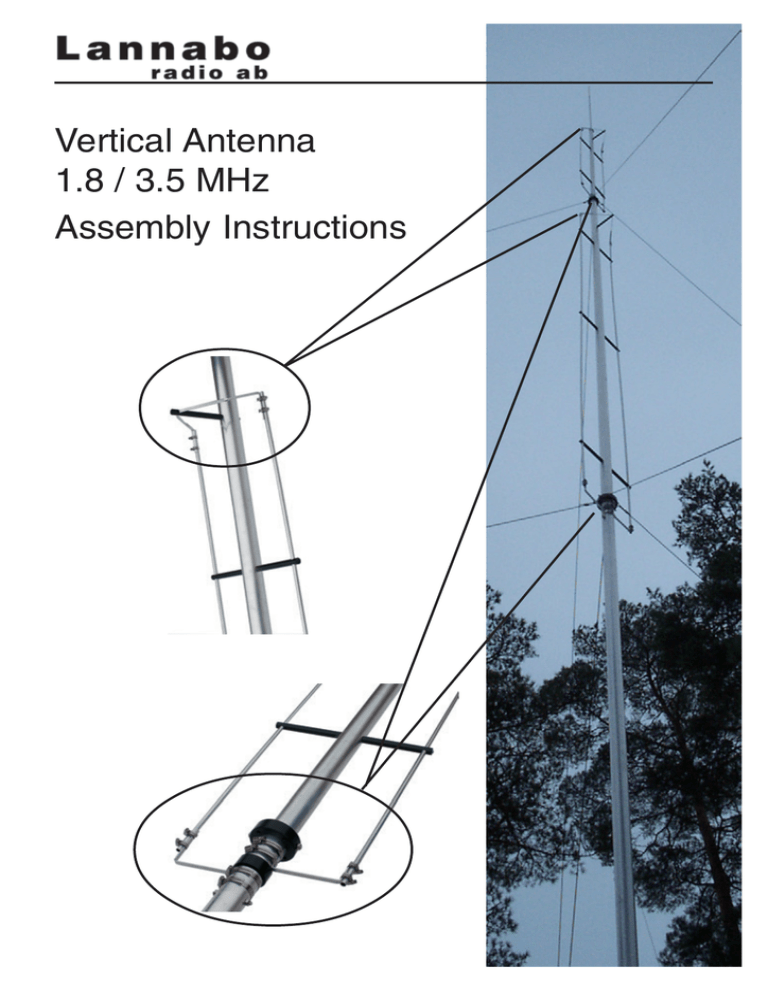
Vertical Antenna 1.8 / 3.5 MHz Assembly Instructions Assembly Assemble the three tubes i.e. 60mm + 60mm + 45mm (o.d) including separation insulators and guy wire rings. Note; colour coding! Install the insulators for the linear loading elements. Note that insulators with M4 machine screws at the ends should be close to the separation insulators. Do not over-tighten and refrain from using tool as this may cause permanent damage to the insulators. Install the 12mm ( o.d. ) tubings intended for linear loading and the connecting straps according to picture. Observe 4mm holes in tubing intended for securing in insulators. Note, there are two different sizes of straps, one for lower linear loading and one for upper linear loading. Do not overtighten hose clamps as they might be damaged. Lower end of linear loading Upper end of linear loading Guy Wires Antenna requires two complete sets of guy-wires at different levels 6m and 12m. Guy-wire anchor, four are recommended, should be located a minimum distance of 6m from base mount. None conductive material are prefered for all guy-wires e.g. Parafil or Kevlar. If metallic guys are used, it is recommended these be broken up with “egg” insulators at regular intervals to shorten the effective wavelenght of each wire and thus reduce any degradation to the antenna radiation pattern. Tuning Unit The unit is designed to match the antenna system to a 50 ohm unbalanced load, i.e a coaxial feedline. The coil is tuning the antenna for 1.8MHz. The capacitator is tuning the antenna for 3.5MHz Large wire with soldering lug should be connected to radiator. coil taps capacitor Tuning the antenna Note that the taps on the coil and the tuning capacitor must be adjusted for lowest VSWR at the preferred frequency after completing the installation. Radial ( ground ) system The small wire from the tuning unit should be connected to radial ( ground ) system. A minimum number of sixteen radials are required on ground; eight 40m long and eight 20m long. Band switching Band switching relay supply voltage is 24 VDC. Also note that 24 VDC must be permanently connected to relay during antenna use. Yellow/green wire is for minus 24 DC. Blue wire is for positive 24 VDC in 3.5MHz position. Brown wire is for positive 24 VDC in 1.8MHz position. (note picture ) 1,8 / 3,5 MHz band switch Blue Brown + 24 VDC Yellow/green To Tuning Unit Base Mount Stainless steel base mount must be installed and secured to rock layer or concrete slab using M12 ( 12mm ) threaded galvanized or stainless steel rods with appropriate washers and nuts. Two insulators are secured to rear of base mount. These are intended for installing tuning unit. Lannabo Radio AB Karnelundsvägen 97 430 33 FJÄRÅS SWEDEN Tel: +46 300 54 11 29, E-mail: info@lannabo.se WARNING HIGH VOLTAGE EXISTS ON THE RADIATOR DURING TRANSMIT EVEN WITH LOW POWER ( 100 WATTS ). MEASURES MUST BE TAKEN TO PREVENT PEOPLE OR ANIMALS FROM TOUCHING THE RADIATOR. SEVERE BURNS MAY RESULT. The antenna should be checked periodically for wear and tear. In particular, the condition of the guy wires ( if steel wire is used ) should be checked, especially in locations where the antenna is subject to “salty air” from the sea. All terminations and connecting straps should also be checked as well as the condition of the coaxial cable feeding the antenna.

