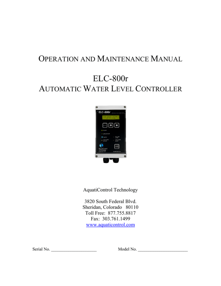
ELC-800r Manual
advertisement

OPERATION AND MAINTENANCE MANUAL ELC-800r AUTOMATIC WATER LEVEL CONTROLLER AquatiControl Technology 3820 South Federal Blvd. Sheridan, Colorado 80110 Toll Free: 877.755.8817 Fax: 303.761.1499 www.aquaticontrol.com Serial No. _____________________ Model No. _______________________ TABLE OF CONTENTS Introduction ................................................................................... 3 Installation ................................................................................. 4-5 Wiring Diagram ...............................................................................6 Operation .................................................................................... 7-8 Routine Maintenance .................................................................... 9 Troubleshooting .................................................................... 10-11 Warranty ..................................................................................... 12 -2ACT 2009 INTRODUCTION The AquatiControl Technology (ACT) Model ELC-800r is designed to provide the most accurate and reliable automatic water level control for swimming pools, spas, fountains, and spray pads. All of the user-friendly features incorporated into the system were designed with the operator in mind. The importance of precise control of water level in relation to proper filtration and water chemistry makes it possible to appreciate a device that will maintain levels within +/- 1/8 of an inch. Installing the system requires basic tools and is accomplished quickly. Installation and operating instructions can be found on the following pages of this manual. Line drawings for each sensing configuration can be found on our website at www.aquaticontrol.com. The ELC-800r should ship with the following contents: (1) (1) (1) (1) (1) Control unit Sensing Unit Standard Well Sight Glass Wet Well Surge Tank Deck Well Mounting Hardware Operation and Maintenance Manual Warranty Card If any items are not found in this package, please call your closest distributor or the factory at (303) 762-9470. ELC-800r-SW Standard Well Sensing unit 5' ½” Polytubing 1/2" PVC ball valve 2- 1/2" Parker fittings 1/2"x close Nipple TBE Mounting hardware 25' remote cable ELC-800r-DW Deck Well Sensing well Sensing box ELC-800r-SG Sight Glass Sensing box 25' remote cable 25' remote cable -3ACT 2009 ELC-800r-WW Wet Well Sensing stick Compression Fitting 25' remote cable ELC-800r-ST Surge Tank Sensing stick 2- 1" Clic clamps Mounting hardware 25' remote cable INSTALLATION The controller and sensing unit should be securely mounted on a sound surface. The controller should be mounted within five feet of a 120 VAC, 60 Hz grounded outlet. The controller can be wired up to 300 feet from sensor unit (contact ACT for exceptions). ACT recommends mounting the controller in the most favorable environment possible. The standard well sensing unit is installed at the water level of the pool. The center of the clear ½” PVC tube on the sensing unit should be at the normal operating water level of the pool. An isolated static water line from the pool to the sensing unit is necessary to provide stable water conditions. A valve arrangement is provided. The valves are installed so that the operator may maintain and clean the sensing unit. The sight glass sensing unit is installed by attaching the unit to a balance tank sight glass. The sensor should be mounted at normal operating water level of the balance tank using the included clic connectors. The wet well sensing unit is installed in a 2” PVC pipe which serves as a still water stand pipe from the pool. The normal water level should sit approximately 1 ½” from the bottom of the end cap. The surge tank sensing unit is installed in the surge tank at normal operating water level with the included clic connectors. The normal water level should sit approximately 1 ½” from the bottom of the end cap. The deck well sensing unit is installed at pool side. The unit has a ½” static line sight glass inside to attach a sight glass sensing unit to (sensing unit and sight glass provided). The deck well is connected to the pool using a 2” static line. Conduit connection and drain connections are also present to make installation quick and easy. The three conductor extension cable provided with the system is the electrical connection for the sensor unit to the controller. With the standard well, sight glass, wet well and deck well, a terminal strip is provided in the sensor housing for terminating the cable (a wiring diagram is located inside sensor box for standard well, sight glass, wet well, and deck well applications). The other end of the cable terminates inside the ELC800r. The interconnecting cable carries low voltage. Local codes may require the cable to be housed in conduit. Refer to www.aquaticontrol.com for sensing applications, drawings, and other product information offered by AquatiControl Technology. -4ACT 2009 CONNECTING THE SOLENOID VALVE The ELC-800r unit will actuate up to a 2” solenoid valve with a 24 VAC, 10 watt (max) supply, without the use of an auxiliary relay. AquatiControl Technology recommends an anti-water hammer or slow close solenoid valve. The power and ground cables should be directly connected to the ELC-800r terminal strip. Refer to www.aquaticontrol.com for a full line of solenoid valves. CONNECTING LOW WATER FEATURE The ELC-800r has a low water feature that incorporates a NC/NO relay located inside the control unit. The relay is used to interrupt the power to a pump in case of a low water situation or it can be wired to an alarm, light or sounder. PUMP CUT-OFF The ELC-800r has incorporated a 24VAC output and relay to allow for a low water setting to shut off a circulation pump in a low water situation. A 24VAC contactor in line with the pump is needed and not supplied. Also required is another sensing unit that will suit the needs of the body of water. The second sensing unit should be placed at chosen low water level and adjusted. Once the sensor and contactor are in place and wired they can be connected to the ELC-800r using the provided wiring diagram. ALARM/LIGHT/SOUNDER The ELC-800r has incorporated a 24VAC output and relay to allow for a low water setting to turn on an alarm, light, or sounder in a low water situation. A separate 24VAC alarm, light or sounder is needed for this feature. Also required is another sensing unit that will suit the needs of the body of water. The second sensing unit should be placed at chosen low water level and adjusted. Once the sensor and alarm, light, or sounder are in place and wired they can be connected to the ELC-800r using the provided wiring diagram. -5ACT 2009 Wiring Diagram Input/Output Terminal Relay Common 11 12 13 14 15 Low Level Sensor – Red Wire 24VAC 10 Low Level Sensor – Green Wire 24VAC 9 Low Level Sensor – Black Wire Ground 8 Normal Level Sensor – Red Wire 7 Normal Level Sensor – Green Wire 6 Normal Level Sensor – Black Wire 5 Relay Normally Closed 4 Relay Normally Open 3 Fill Valve 24VAC Fill Valve Ground 2 Fill Valve 24VAC 1 Single Level Control Normal Level Sensor attaches to normal level sensor terminals (#’s 10,11,12) & Fill Valve attaches to fill valve terminals (#’s 1,2,3). Dual Level Control Normal Level Sensor attaches to normal level sensor terminals (#’s 10,11,12) & Fill Valve attaches to fill valve terminals (#’s 1,2,3). Low Level Sensor attaches to low level sensor terminals (#’s 13,14,15). • • Low Water Pump Cut Off – 24VAC (#5) to pump contactor (supplied by others), 24VAC (#6) jump to Relay Common (#7), & Relay Normally Closed (#9) to pump contactor (supplied by others). Low Water Alarm – 24VAC (#5) to 24VAC Alarm, Light or Sounder (supplied by others), 24VAC (#6) jump to Relay Common (#7), & Relay Normally Open (#8) to 24VAC Alarm, Light or Sounder (supplied by others). -6ACT 2009 OPERATION Once installation has been completed as described on the previous pages, open the water supply valve to sensor unit. If the water is not up to ideal level in the pool, manually adjust the water level to that point. After level is set and water is at normal operating water level, it is time to power the control unit. Plug the unit into the 120 VAC, 60 Hz electrical outlet then proceed to turn the on/off toggle switch on the side of the controller to the ON position. The unit will go through a self-test and beep to let the user know it is on and ready. Once power is applied to the controller there are settings in the menu that can be changed. The user can scroll through the menu by pressing the select button. Options can be changed using the up and down arrows. FILL ON DELAY (time between sensor not sensing water and fill solenoid opening) Fill on delay can be set from 15 seconds to 99 seconds. DEFAULT: 15 seconds MAX FILL TIME (maximum time solenoid valve is allowed to stay on per fill cycle) Max fill time can be set from 20 minutes to 240 minutes, or continuous. DEFAULT: 30 minutes FILL OFF DELAY (time solenoid stays on after sensor begins sensing water) Fill off delay can be set from 2 seconds to 99 seconds. DEFAULT: 5 seconds LOW WATER DELAY (time required before low alarm is triggered) Low water delay can be set from 10 seconds to 99 seconds. DEFAULT: 15 seconds LOW WATER ALARM RESET AUTOMATIC – ELC will continue normal operation once water level reaches at least low water sensor (no additional actions required by user). MANUAL – ELC will not continue normal operation until the alarm reset button is pressed (even once the Low Level Sensor senses water). DEFAULT: Automatic SOUNDER WITH ALARM (beeping will occur when in alarm mode if yes is selected) Yes or No DEFAULT: Yes SENSOR TYPE (set to Other) DEFAULT: Other LOW WATER SENSOR (enables low level feature option) No and Yes -7ACT 2009 DEFAULT: No LCD ADJUST FOR VIEWING ANGLE (changes the contrast of the LCD) LCD adjust can be set from 01 to 20. DEFAULT: 05 RESET PASSWORD (enables password protection of settings) NONE – No password required to change settings NEW- Enter up to 8 digit (0-9) password If the password is forgotten the user can perform a master reset by turning the unit on while holding the up and down arrows (this will reset all settings to the default settings). DEFAULT: None -8ACT 2009 ROUTINE MAINTENANCE AquatiControl Technology’s Model ELC-800r controller is completely solid state and normally will not require any maintenance. SENSOR UNIT CLEANING STANDARD WELL The ½” PVC tube on the Standard Well Sensing Unit may need to be cleaned periodically. To clean the tube, isolate the sensor unit by closing the valve that supplies the water to it. Remove the cap from the top of the tube and fill with a diluted acid solution, 3 parts water to 1 part acid. A brush may be used to clean the inside of the tube. The valve at the bottom of the sensing unit can be opened to drain out the acid solution. Place the solution into a container and dispose of it properly. The tube can then be flushed with fresh water. After flushing, open the valve from the pool. The unit is now ready for operation. SIGHT GLASS The Sight Glass Sensing Unit will not normally need to be cleaned. SURGE TANK The Surge Tank Sensing Unit will not normally need to be cleaned, however, if the cap on the bottom of the sensing application becomes clogged with debris it can be unscrewed and rinsed until clean and then replaced. WET WELL The Wet Well Sensing Unit will not normally need to be cleaned; however, if the cap on the bottom of the sensing application becomes clogged with debris it can be unscrewed and rinsed until clean and then replaced. DECK WELL The Deck Well Sensing Unit will not normally need to be cleaned; however, debris and stagnant water may enter the Deck Well which can be cleaned out being very careful not to get any water near the sensing unit or electrical conduit. SENSOR REPLACEMENT The proximity switch used for the control system is normally good for thousands of on and off switches. Typically the sensor should be replaced every three years for year round usage. Seasonal pools may require replacing every five years or as needed. Replacement sensors are available from distributors and the factory. -9ACT 2009 TROUBLESHOOTING SYMPTOM POSSIBLE CAUSE Plugged into a dead outlet Check outlet power and switch setting on controller Bad system fuse Replace fuse Fill is in delay Normal operation for ELC800r Water supply flow is too low Increase flow Solenoid not opening Repair/replace valve Exceeded maximum time on alarm sequence Increase setting Sensing unit not set properly Readjust sensor to desired water level Supply valve to sensor valve shut off Turn on valve Defective sensor Replace sensor Sensing unit not set properly Readjust sensor to desired water level No power to controller Filling light flashing Frequent fill time alarm Normal operating water level too low Level light does not come on Level light continually on Hammering of water supply Solenoid valve does not activate Low water pump cutoff does not work CORRECTIVE ACTION Wiring is incorrect in sensor Check wiring connection junction box Cable in ELC-800r controller wired improperly Check wiring connection Sensing unit is dirty Clean sensing unit Defective sensor Replace sensor Install slow close solenoid valve Check voltage on valve 24 VAC (10 watts max) Clean or replace valve or coil Water pressure is too high Bad system fuse Defective solenoid Wiring is incorrect in ELC or at contactor Check wiring connection Feature not turned on Change setting in menu options - 10 ACT 2009 SYMPTOM POSSIBLE CAUSE CORRECTIVE ACTION Can not change settings Forgotten/wrong password Reset ELC by turning the power on while holding the up and down arrows ELC does not allow pump to turn on ELC is still in alarm and needs to be reset Press alarm reset button - 11 ACT 2009 WARRANTY AquatiControl Technology (ACT) warrants equipment of its manufacture and bearing its identification to be free of defects in workmanship and material. ACT’s liability under this warranty extends for a period of one year from date of delivery from our factory or authorized distributor. It is limited to repairing or replacing any device or part which is returned, transportation prepaid, to the factory within one year of delivery to the original purchaser, and which is proven defective upon examination. ACT disclaims all liability for damage during transportation, for consequential damage of any nature, for damage due to handling, installation or improper operation, and for determining suitability for the use intended by the purchaser. ACT makes no warranties, expressed or implied, other than those stated above. No representative has authority to change or modify this warranty in any respect. - 12 ACT 2009


