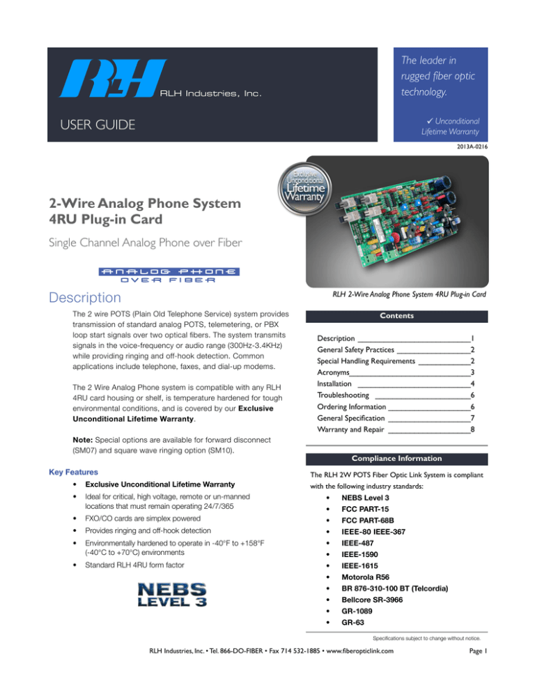
2-Wire Analog Phone System 4RU Plug-in Card
advertisement

The leader in rugged fiber optic technology. RLH Industries, Inc. Unconditional Lifetime Warranty USER GUIDE 2013A-0216 2-Wire Analog Phone System 4RU Plug-in Card Single Channel Analog Phone over Fiber 3@3>A9 B:A@7 &-) ) Description RLH 2-Wire Analog Phone System 4RU Plug-in Card The 2 wire POTS (Plain Old Telephone Service) system provides transmission of standard analog POTS, telemetering, or PBX loop start signals over two optical fibers. The system transmits signals in the voice-frequency or audio range (300Hz-3.4KHz) while providing ringing and off-hook detection. Common applications include telephone, faxes, and dial-up modems. The 2 Wire Analog Phone system is compatible with any RLH 4RU card housing or shelf, is temperature hardened for tough environmental conditions, and is covered by our Exclusive Unconditional Lifetime Warranty. Contents Description __________________________1 General Safety Practices _________________2 Special Handling Requirements ____________2 Acronyms ____________________________3 Installation __________________________4 Troubleshooting ______________________6 Ordering Information ___________________6 General Specification ___________________7 Warranty and Repair ___________________8 Note: Special options are available for forward disconnect (SM07) and square wave ringing option (SM10). Compliance Information Key Features The RLH 2W POTS Fiber Optic Link System is compliant • Exclusive Unconditional Lifetime Warranty • Ideal for critical, high voltage, remote or un-manned locations that must remain operating 24/7/365 • NEBS Level 3 • FCC PART-15 • FXO/CO cards are simplex powered • FCC PART-68B • Provides ringing and off-hook detection • IEEE-80IEEE-367 • Environmentally hardened to operate in -40°F to +158°F (-40°C to +70°C) environments • IEEE-487 • IEEE-1590 Standard RLH 4RU form factor • IEEE-1615 • Motorola R56 • BR 876-310-100 BT (Telcordia) • Bellcore SR-3966 • GR-1089 • GR-63 • with the following industry standards: Specifications subject to change without notice. RLH Industries, Inc. • Tel. 866-DO-FIBER • Fax 714 532-1885 • www.fiberopticlink.com Page 1 General Safety Practices Intended Audience This guide is intended for use by knowledgeable telco/network installation, operation and repair personnel. Every effort has been made to ensure the accuracy of the information in this guide is accurate. However, due to constant product improvement, specifications and information contained in this document are subject to change without notice. Conventions Symbols for notes, attention, and caution are used throughout this manual to provide readers with additional information, advice when special attention is needed, and caution to prevent injury or equipment damage. The equipment discussed in this document may require tools designed for the purpose being described. RLH recommends that service personnel be familiar with the correct handling and use of any installation equipment used, and follow all safety precautions including the use of protective personal equipment as required. Caution - Severe Shock Hazard • Never install during a lightning storm or where unsafe high voltages are present. • Active phone lines may carry high DC voltages. Use caution when handling copper wiring. HVP Warning The intra-building port(s) of the equipment or subassembly is suitable for connection to intrabuilding or unexposed wiring or cabling only. The intra-building port(s) of the equipment MUST NOT be metallically connected to interfaces that connect to the OSP or its wiring. These interfaces are designed for use as intra-building interfaces only (Type 4 ports as described in GR-1089-CORE, Issue 4) and require isolation from the exposed OSP cabling. The addition of Primary Protectors is not sufficient protection in order to connect these interfaces metallically to OSP wiring. Special Handling Requirements Be careful when handling electronic components ATTENTION ELECTROSTATIC SENSITIVE DEVICES • This product contains static sensitive components. • Handle Fiber Optic Link cards at their edges only. • Follow proper electrostatic discharge procedures. This card utilizes circuitry that can be damaged by static electricity. When transporting the card, carry it in an ESD safe container such as the antistatic bag provided with the card. Before handling cards, discharge yourself of static electricity by physical bodily contact with earth ground. When handling cards, hold by outer edges and avoid touching circuitry. Failure to follow ESD precautions may cause serious damage to the card and prevent proper operation. RLH Industries, Inc. • Tel. 866-DO-FIBER • Fax 714 532-1885 • www.fiberopticlink.com Page 2 Guidelines for handling terminated fiber cable • Do not bend fiber cable sharply. Use gradual and smooth bends to avoid damaging glass fiber. • Keep dust caps on fiber optic connectors at all times when disconnected. • Do not remove dust caps from unused fiber connectors. • Keep fiber ends and fiber connectors clean and free from dust, dirt and debris. Contamination will cause signal loss. • Do not touch fiber connector ends. • Store excess fiber on housing spools or fiber spools at site Acronyms Commonly used acronyms and abbreviations Acronym/Abbreviation POTS Description Plain Old Telephone Service (analog phone) FXO/CO Foreign Exchange Office or Central Office location FXS/Sub Foreign Exchange Station or Subscriber side location PBX Private Branch Exchange TX Transmit RX Receive CPE Customer Premises Equipment MM Multimode SM Single Mode 2W 2 wire copper analog phone line RU EIA Rack Space Unit (1.75”) RLH Industries, Inc. • Tel. 866-DO-FIBER • Fax 714 532-1885 • www.fiberopticlink.com Page 3 Installation Prior to installation: Check for shipping damage: • Check the contents to ensure correct model and fiber type • Have a clean, dry, installation environment ready Required for installation: • 24~56VDC (200mA@24VDC min.) local power source for the FXS/Sub card • RLH 4RU card housing or enclosure • A weatherproof enclosure is required for outdoor use The 2-wire POTS 4RU card can be installed into any compatible RLH card housing. All electrical and fiber optic connection are made directly onto the card. 2-Wire POTS FXO/CO (Central Office) Side Card The 2-Wire POTS FXO/CO Card provides the electrical-optical interface between a Central Office or PBX 2-wire copper line and two optical fiber strands. The FXO/CO card is powered by 2-wire talk battery (18VDC 0.5mA on-hook/ 18mA off-hook minimum) current. Note: If sealing current is not present, the 2-wire POTS Power Coupler (P/N: 8806-1252-01, 8806-1252-02) must be used to insert simplex DC power onto the 2-wire line. Note: To maintain high voltage isolation, Fiber Optic Link FXO/CO and FXS/Sub cards must be powered from separate isolated power sources. 2-Wire POTS FXS/Sub (Subscriber) Side Card. The 2-Wire POTS Sub Card provides the optical-electrical interface between the two fiber strands and a 2-wire copper line to a telephone, fax, or modem. The FXS/Sub card is powered by a local 24-56VDC source. The FXS/Sub Card provides 90VRMS sine wave ringing (REN 5.0 max 80VRMS). Square wave ringing is available as an option. LED Indicators on the card display power, ringing and off-hook conditions. The FXS/Sub card is switchable between 14V or 48V power to the telephone port. 2-Wire POTS System Diagram RLH Industries, Inc. • Tel. 866-DO-FIBER • Fax 714 532-1885 • www.fiberopticlink.com Page 4 Connect fiber optic cable The 2 Wire POTS Cards are each equipped with two optical connectors. Connect the fibers to the transmitter and receiver marked TX and RX respectively. The TX connector of one card is connected to the RX connector of the card at the other end. Refer to the 2-Wire POTS System Diagram. Note: Fiber cable should always be routed loosely avoiding tight bends. 2-Wire Analog Phone FXO/CO Card Connectors 2-Wire Analog Phone FXS/Sub Connectors Connect 2-wire copper pair The copper pair from the FXO/CO or PBX connects to the green LINE screw-down terminal on the FXO/ CO Card. The LINE connector on the FXO/CO card is not polarity sensitive The copper pair from the telephone connects to the green TELEPHONE and screw-down terminals on the FXS/Sub Card. Attach the copper pair, + is for TIP and - is for RING. Make connections according to the polarity markings on the connector. Connect Power Connect a 24-56VDC (200mA minimum) power source to the black “AUX. P.S.” screw-down terminal on the Sub card. Note: The power input is polarity sensitive and marked with positive and negative. RLH Industries, Inc. • Tel. 866-DO-FIBER • Fax 714 532-1885 • www.fiberopticlink.com Page 5 SW2 Switch OFF for 14V, or ON for 48V telephone output Red LED remains ON in off-hook state Orange SUB CXR LED Green CO CXR LED SW1 Remains OFF unless using with CO card Forward Disconnect option (SM09). Yellow Ring/BR Relay LED Blue Card Power LED Telephone, green terminal is for a copper pair. + = TIP / - = RING FXS/Sub LED indicators and switches Switches There are 2 user settable switches on the FXS/Sub card. SW1 is only used together with a FXO/CO card that has the SM09 Forward Disconnect option. Set the switch to OFF in standard systems, and ON when using with the FXO/CO card with forward disconnect. SW2 sets the telephone terminal output voltage. This can be useful in situations where power consumption is an issue. Set the Switch to OFF to operate in low power mode, with 14V telephone output. This is the default setting, and requires only approximately 4mA from the power supply. Note: Remove power from the power connector before changing the SW2 setting. Set the switch to ON for normal 48V operation. This simulates typical CO output and is useful for long distance or where connected equipment requires 48V. The telephone output current is always limited to 23mA regardless of the setting. RLH Industries, Inc. • Tel. 866-DO-FIBER • Fax 714 532-1885 • www.fiberopticlink.com Page 6 LED Indicators The FXS/Sub card has several LED indicators to help determine card operation. Please refer to the LED indicators and switches diagram and the function chart below. Indicator Color State CO CXR Green Flashing OFF SUB CXR RING/BR RELAY CARD POWER ~ Orange Yellow Red On-hook - no incoming signal from FXO/CO card Off-hook - Incoming call ON Off-hook OFF On-hook - no outgoing signal from FXO/CO card ON Off-hook OFF On-hook - no signal to or from FXO/CO card Flashing Blue Description Off-hook - Incoming call ON Off-hook - call is answered ON Power is present OFF No power is present or polarity is reversed ON Off-hook power indicator OFF On-hook power indicator Troubleshooting If trouble is encountered, verify all copper and fiber connections and settings. If trouble persists, replace the unit and retest. If technical assistance is required, contact RLH Industries, Inc. technical support department. Ordering Information RLH Fiber Optic Link products are available directly through RLH Industries, Inc. or its distributors nationwide. Please call RLH customer service for ordering assistance. Each 2W POTS card is identified with the part number. 2W POTS FXO/CO Card Fiber Type Max. Distance Multimode ST * 1.5 miles (2.5km) 8806-1234-03 Multimode SC * 1.5 miles (2.5km) 8805-1234-03 Single-mode ST 9 miles (15km) 8806-1261-01 Single-mode ST (Long Haul) 37 mi. (60 km) 8806-1261-01LH Single-mode SC 9 miles (15km) 8805-1261-01 Single-mode SC (Long Haul) 37 mi. (60 km) 8805-1261-01LH Part Number CLEI Code 2W POTS FXS/Sub Card Part Number NPIFA301AA 8806-1244-05 – – NPIFDB01AA 8806-1271-03LH NPIFKD01AA 8805-1271-03 – NPIFAB401AA 8805-1244-05 NPIFCB01AA 8806-1271-03 – CLEI Code – NPIFLD01AA 8805-1271-03LH – * 62.5µm multimode fiber compatibility is standard, add -50 to part number for 50µm fiber compatibility. Add RJ to part number for installed RJ11 adapter. Add -SM07 to part number for forward disconnect option. Add -SM10 to part number for square wave ringing option. RLH Industries, Inc. • Tel. 866-DO-FIBER • Fax 714 532-1885 • www.fiberopticlink.com Page 7 General Specifications Transmission method Maximum Fiber Loss / Distance* Frequency modulated light via Multimode 850nm (Tx level: -16dB ± 1dB) two optical fibers Single-mode: 1310nm (Tx level: -23dB ± 1dB) SM Long Haul: 1310nm (Tx level: -8dB ± 2dB) Multimode: 10dB / 1.5 miles (2.5km) Single-mode: 8dB / 9 miles (15km) SM Long Haul: 26dB* / 37 mi. (60 km), *min. required loss -8dB * Note: Distances equated using industry standard fiber and connector attenuation of 3dB/ Km. Fiber condition, splices and connectors may affect actual range. Fiber Type Multimode: 62.5/125μm, 50/125μm Single-mode: 8-9/125μm Fiber Connector Types ST or SC Wire Connector Screw clamp, 12-26 AWG Bandwidth 300 Hz to 3.4 KHz Dialing Protocol Pulse or tone dialing Ringing Sine wave matched to input frequency, REN 5.0 Square wave ringing option available - SM10 Drop Voltage / Current Source voltage selectable between 48V and 14V (power saving) 22± 1mA Insertion Loss 0dB +/- 0.5dB each direction Surge Protection PTC thermistors, zener diodes and varistors Power Requirements CO Card: 18-56VDC, On-hook 0.5mA maximum, off-hook 18mA minimum (card will sink up to 30mA line seizure). Powering Method Sub Card: 24-56VDC, 200mA maximum CO Card: Line Power (DC Simplex or Talk Battery) Sub Card: Local Power Supply Operating Temperature -40° to +158° F (-40° to +70° C), 95% non-condensing Dimensions RLH Standard 4RU Card Form Factor (7”x4”x1”) RLH Industries, Inc. • Tel. 866-DO-FIBER • Fax 714 532-1885 • www.fiberopticlink.com Page 8 Warranty RLH is recognized throughout the U.S. and offers the only UNCONDITIONAL LIFETIME WARRANTY in the telecommunications industry. We are very proud of our warranty which simply states that our Fiber Optic Link Assemblies are warranted to be free of defects in material and workmanship for the LIFE OF THE PRODUCT. We can offer this warranty because: • • • • We We We We believe our customers shouldn't have to incur additional costs due to failure or damage engineer and manufacture our Fiber Optic Links in the USA, with total confidence in our quality understand how safety and reliability impact the total cost of ownership know that customer support extends beyond the initial sale, so we stand behind our products RLH will replace any product, or part thereof, that fails FOR ANY REASON, provided the defective part is returned to RLH Freight prepaid. This warranty is UNCONDITIONAL and valid even when RLH Fiber Optic Link Assemblies have been abused or mishandled, where unauthorized repairs have been attempted or performed, or product has been damaged as a result of a natural disaster. Compare this warranty to our competitors and see how our warranty will reduce your costs and simplify your maintenance activities. To make a warranty claim, or schedule repair or replacement of your RLH product, please contact us for an RMA number. You will be promptly assisted by one of our warranty specialists. All returns must have an RMA number before we can receive any items. Technical Support Normal technical support: Local (714) 532-1672 (Mon - Fri 6am - 6pm PST) Toll Free (800) 877-1672 Toll Free (866) DO-FIBER 24/7 Technical support: (714) 396-8982 (714) 457-5740 Contact Information Corporate Headquarters: RLH Industries, Inc. 936 N. Main Street Orange, CA 92867 USA Phone: Local (714) 532-1672 Toll Free (800) 877-1672 Toll Free (866) DO-FIBER Fax: (714) 532-1885 Email: info@fiberopticlink.com Web site: www.fiberopticlink.com RLH Industries, Inc. • Tel. 866-DO-FIBER • Fax 714 532-1885 • www.fiberopticlink.com Page 9 RLH Industries, Inc. 936 N. Main Street, Orange, CA 92867 USA T: (714) 532-1672 F: (714) 532-1885 Please contact your RLH sales representative for pricing and delivery information. Specifications subject to change without notice. RLH Industries, Inc. • Tel. 866-DO-FIBER • Fax 714 532-1885 • www.fiberopticlink.com Page 10


