Series Resonant Converter
advertisement

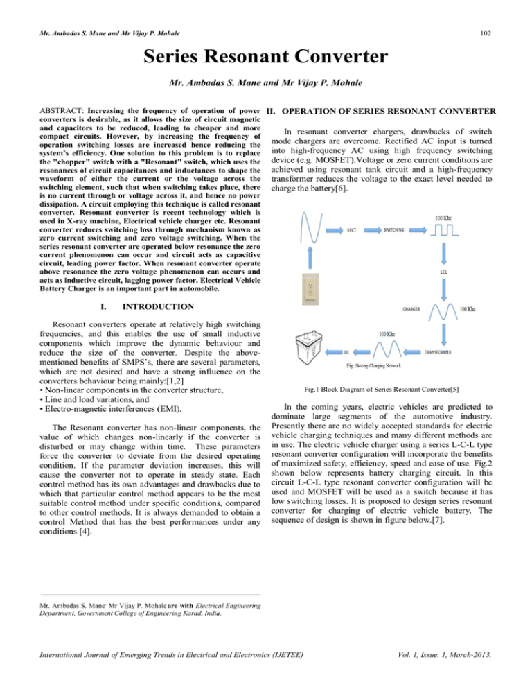
Mr. Ambadas S. Mane and Mr Vijay P. Mohale 102 Series Resonant Converter Mr. Ambadas S. Mane and Mr Vijay P. Mohale ABSTRACT: Increasing the frequency of operation of power II. OPERATION OF SERIES RESONANT CONVERTER converters is desirable, as it allows the size of circuit magnetic and capacitors to be reduced, leading to cheaper and more In resonant converter chargers, drawbacks of switch compact circuits. However, by increasing the frequency of mode chargers are overcome. Rectified AC input is turned operation switching losses are increased hence reducing the system’s efficiency. One solution to this problem is to replace into high-frequency AC using high frequency switching the "chopper" switch with a "Resonant" switch, which uses the device (e.g. MOSFET).Voltage or zero current conditions are resonances of circuit capacitances and inductances to shape the achieved using resonant tank circuit and a high-frequency waveform of either the current or the voltage across the transformer reduces the voltage to the exact level needed to switching element, such that when switching takes place, there charge the battery[6]. is no current through or voltage across it, and hence no power dissipation. A circuit employing this technique is called resonant converter. Resonant converter is recent technology which is used in X-ray machine, Electrical vehicle charger etc. Resonant converter reduces switching loss through mechanism known as zero current switching and zero voltage switching. When the series resonant converter are operated below resonance the zero current phenomenon can occur and circuit acts as capacitive circuit, leading power factor. When resonant converter operate above resonance the zero voltage phenomenon can occurs and acts as inductive circuit, lagging power factor. Electrical Vehicle Battery Charger is an important part in automobile. I. INTRODUCTION Resonant converters operate at relatively high switching frequencies, and this enables the use of small inductive components which improve the dynamic behaviour and reduce the size of the converter. Despite the abovementioned benefits of SMPS’s, there are several parameters, which are not desired and have a strong influence on the converters behaviour being mainly:[1,2] • Non-linear components in the converter structure, • Line and load variations, and • Electro-magnetic interferences (EMI). The Resonant converter has non-linear components, the value of which changes non-linearly if the converter is disturbed or may change within time. These parameters force the converter to deviate from the desired operating condition. If the parameter deviation increases, this will cause the converter not to operate in steady state. Each control method has its own advantages and drawbacks due to which that particular control method appears to be the most suitable control method under specific conditions, compared to other control methods. It is always demanded to obtain a control Method that has the best performances under any conditions [4]. Fig.1 Block Diagram of Series Resonant Converter[5] In the coming years, electric vehicles are predicted to dominate large segments of the automotive industry. Presently there are no widely accepted standards for electric vehicle charging techniques and many different methods are in use. The electric vehicle charger using a series L-C-L type resonant converter configuration will incorporate the benefits of maximized safety, efficiency, speed and ease of use. Fig.2 shown below represents battery charging circuit. In this circuit L-C-L type resonant converter configuration will be used and MOSFET will be used as a switch because it has low switching losses. It is proposed to design series resonant converter for charging of electric vehicle battery. The sequence of design is shown in figure below.[7]. Mr. Ambadas S. Mane, Mr Vijay P. Mohale are with Electrical Engineering Department, Government College of Engineering Karad, India. International Journal of Emerging Trends in Electrical and Electronics (IJETEE) Vol. 1, Issue. 1, March-2013. Mr. Ambadas S. Mane and Mr Vijay P. Mohale 103 Fig.2 Circuit Diagram of Series Resonant Converter[7] The aim of this project is to develop a fast and efficient method of electric vehicle battery charger using L-C-L type Resonant Converter topology. For ease of use, the entire system will be monitored by microcontroller which will control the power output of the charger and monitor the state SI of batteries to protect system from line born disturbances. 1. Zero –voltage switching: When the series resonant converter is operated above resonance, the zero voltage switching phenomenon’s can occur, in which the circuit causes the transistor voltage to become zero before the controller turns the transistor on. With the minor circuit modification, the transistor turn-off transition can also be caused to occur at zero voltages. This process can lead the significant reductions in the switching losses of converters based on MOSFETs & Diodes. For the full bridge circuit of fig13.theswitch output voltage Vs (t), &its fundamental component Vsl (t), as well as the approximately sinusoidal tank current waveform is (t), are plotted in fig18. For the half cycle 0<t<Ts/2, the switch voltage Vs (t) is equal to +Vg. For 0<t<ta, the current Is (t) is negative & diodes D1 & D4 conduct. Transistor Q1& Q4 conduct when Is (t) is positive, over the interval ta<t<Ts/2.The waveform during Ts/2<t<Ts are symmetrical. Since the zero crossing of Vs (t) leads the zero crossing of Is (t), the transistor conduct after their respective anti parallel diode. In general, zero voltage switching can occurs. When the resonant tank present an effective inductive load to the switches, & hence the switch voltage zero crossing occur before the switch current zero crossing. The transistor turn-off transition in fig. is similar to that of PWM switch. In converters the employ IGBTs or other minority-carrier devices, significant switching loss may occur at the turn-off transition. The current tailing phenomenon causes Q1 to pass through a period of high instantaneous power dissipation & switching loss occurs. An additional advantage of zero-voltage switching is the reduction of EMI associated with device capacitance. Fig.3 Switch Network Output Waveforms for Series Resonant Converter III. SINUSOIDAL ANALYSIS OF RESONANT CONVERTERS The class of resonant converters contains a controlled switch network (Ns) which drives a linear resonant tank network (Nr). In resonant inverter, the tank network drives a resistive load . The reactive component of the load impedances, if any, can be effectively incorporated into the tank network. In the case of resonant DC-DC converter, the resonant tank network is connected to an uncontrolled rectifier network (Nr), filter network (Nf), load R. Many well known converters can be represented in this form, which includes the series, parallel, LCC topology. In the most recommended modes of operation, the controlled switch network produces a square wave output voltage Vs (t) whose frequency (Fs) is close to tank network’s resonant frequency (Fr). In the c as where the resonant tank responds primarily to the fundamental component Fs of switch waveform of frequencies Fs. In the case where the negligible response at the harmonic frequencies n(fs), Where n=3, 5, 7….then the tank waveform’s are well approximated by their fundamental components. As shown in the fig.9, this is indeed case where the tank network contains a high Q-resonance at or near the switching frequencies and a low pass characteristics at higher frequencies. Hence neglect harmonics and compute the relationship between the fundamental components of the tank terminal waveforms Vs (t), Is (t), Ir (t) and Vr(t). International Journal of Emerging Trends in Electrical and Electronics (IJETEE) Vol. 1, Issue. 1, March-2013. Mr. Ambadas S. Mane and Mr Vijay P. Mohale 104 1. Controlled switch network model: Fig.4 Ideal Switch Network Fig.6 Switch Network Waveforms Is (t) and Ir (t). Vs1 4Vg V s t sinst Vs1 sinst 4 Vg π n 1,3,5 1 sin n s t n i st t I s 1 sin st Fig.7 Equivalent Circuit For The Switch Network i g t Fig.5 Switch Network Output Voltage Vs (t) and its Fundamental Component Vs1(t) 2 Ts 2 Ts Ts Ts 2 i d s 0 Ts 2 2 I I S1 sin s s d 0 S1 cos IV. s CONCLUSION In order to study and analyze the Switch Mode Control effect on the converter behavior and to compare it to another control method, a comparison will be done for the output voltage and the inductor current responses of the Series LCL International Journal of Emerging Trends in Electrical and Electronics (IJETEE) Vol. 1, Issue. 1, March-2013. Mr. Ambadas S. Mane and Mr Vijay P. Mohale 105 T- type Resonant converter controlled with the PID control and the SMC. Test results will be obtained in steady state and under dynamic conditions. Resonant converters have advantages such as reduction in cost, size and weight of the power supply. Fast transient response, reduction in switching losses, di/dt and dv/dt stresses of power devices gives additional advantages of using resonant converters. It also reduces Electro-Magnetic Interference (EMI). Resonant converter is recent technology which is used in X-ray machine, high HV pulsed load applications, Ozone generation using LCC RC, high-power industrial application of CO2 laser also needs HV power supply, Electrical vehicle charger etc. ACKNOWLEDGEMENT This paper proved to be quite interesting endeavour. There were many people who helped me while preparing paper and I am deeply thankful to our guide Prof. Mr. A.S.Mane who helped us a lot & played central role to cooperate with me. I would also like to thank our Head of the Department Prof. Mr. V.B.Waghmare for his firm support. And I am thankful to whole staff in our department for their help. Also I would like to mention here special thanks to my friends who helped & supported me REFERENCES BOOKS [1] Mohan, N, Undeland, T, Robbins, W. 1989. Power Electronics: Converter, Applications, and Design. JOHN WILEY & SONS, ISBN 0471-61342-8, 1989, USA. [2] R.W. Erickson , Fundamental of power electronics, first edition, Chapman and Hall, ISBN 0-412-08541-0, 1997, New York [3] Mohammad H. Rashid, Power Electronics-circuit devices & applications, Third Edition, PEARSON, ISBN 978-81-317-0246-8, 2009, INDIA PAPERS [4] G.S.N.Raju and Seshagirirao Doradla, “An LCL Resonant converter with PWM Control Analysis, simulation, and Implementation”, IEEE Transactions on Power Electronics, vol.10, No.2 March 1995. [5] Xinke Wu and Zhaomimg Qian, New current driven synchronous rectifier for series parallel resonant(LLC DC-DC converter). [6] A.K.S Bhatt. Senior member IEE Dept. of elect engg. “Analysis and design of LCL Type series resonant converter, Victoria (B.C.) V8W (2Y2) CANADA, 172-173. [7] A.K.S Bhatt. Senior member IEE Dept. of elect engg. “Analysis and design of fixed frequency LCL Type series resonant converter, Victoria (B.C.) V8W(3P6) CANADA, 253-256. [8] Implementation of a series resonant converter with, Bor-Ren, senior member , IEEE, and BO-Ren Hou, Department of electrical engineering National Yunlin University of science and technology, Yunlin 640,Taiwan International Journal of Emerging Trends in Electrical and Electronics (IJETEE) Vol. 1, Issue. 1, March-2013.


