1 WIS transmitter secondary NDS5 30GM 1M V1
advertisement

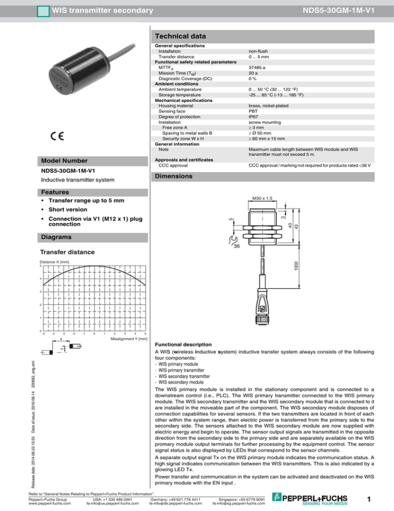
WIS transmitter secondary NDS5-30GM-1M-V1 Technical data General specifications Installation Transfer distance Functional safety related parameters MTTFd Mission Time (TM) Diagnostic Coverage (DC) Ambient conditions Ambient temperature Storage temperature Mechanical specifications Housing material Sensing face Degree of protection Installation Free zone A Spacing to metal walls B Security zone W x H General information Note Model Number Approvals and certificates CCC approval NDS5-30GM-1M-V1 non-flush 0 ... 5 mm 37485 a 20 a 0% 0 ... 50 °C (32 ... 122 °F) -25 ... 85 °C (-13 ... 185 °F) brass, nickel-plated PBT IP67 screw mounting ≥ 3 mm ≥ Ø 50 mm ≥ 60 mm x 15 mm Maximum cable length between WIS module and WIS transmitter must not exceed 5 m. CCC approval / marking not required for products rated ≤36 V Dimensions Inductive transmitter system Features • Transfer range up to 5 mm M30 x 1.5 40 43 5 • Connection via V1 (M12 x 1) plug connection 3 • Short version Diagrams 36 Transfer distance 1000 Distance X [mm] 5 4 3 2 1 0 -5 -4 -3 x -2 -1 0 1 2 3 4 5 Misalignment Y [mm] Release date: 2014-06-23 15:55 Date of issue: 2016-06-14 200662_eng.xml y Functional description A WIS (wireless inductive system) inductive transfer system always consists of the following four components: - WIS primary module - WIS primary transmitter - WIS secondary transmitter - WIS secondary module The WIS primary module is installed in the stationary component and is connected to a downstream control (i.e., PLC). The WIS primary transmitter connected to the WIS primary module. The WIS secondary transmitter and the WIS secondary module that is connected to it are installed in the moveable part of the component. The WIS secondary module disposes of connection capabilities for several sensors. If the two transmitters are located in front of each other within the system range, then electric power is transferred from the primary side to the secondary side. The sensors attached to the WIS secondary module are now supplied with electric energy and begin to operate. The sensor output signals are transmitted in the opposite direction from the secondary side to the primary side and are separately available on the WIS promary module output terminals for further processing by the equipment control. The sensor signal status is also displayed by LEDs that correspond to the sensor channels. A separate output signal Tx on the WIS primary module indicates the communication status. A high signal indicates communication between the WIS transmitters. This is also indicated by a glowing LED Tx. Power transfer and communication in the system can be activated and deactivated on the WIS primary module with the EN input . Refer to “General Notes Relating to Pepperl+Fuchs Product Information”. Pepperl+Fuchs Group USA: +1 330 486 0001 Germany: +49 621 776 4411 fa-info@de.pepperl-fuchs.com www.pepperl-fuchs.com fa-info@us.pepperl-fuchs.com Singapore: +65 6779 9091 fa-info@sg.pepperl-fuchs.com 1 WIS transmitter secondary NDS5-30GM-1M-V1 Additional Information Input signal on EN Function + UB (24 V DC) Transfer activated GND or open. Transfer deactivated Transferable power Power [W] 3 Function schematic 2.5 1 Sensors WIS transmitte r, . . . . . . WIS transmitte r, 1.5 WIS secondary module WIS primary Energy . . . . . . 0.5 Misalignment Y = 0 mm 0 0 Sensor signals 1 x 2 3 4 5 6 Distance X [mm] y Sensor signal output, status output, control input 2 The sum of the currents of all sensors attached to the WIS secondary module must not be greater than the maximum transferable current. This is calculated by dividing the transferable power by the 12 V provided by the transmitters. Installation requirements During operation, the WIS transmitter heats up due to the transfer of electrical energy for the sensor supply from the primary side of the transfer system to the secondary side, primarily by about 40 K above the ambient temperature. By installing the WIS transmitter in metal mounting components heat dissipation can be improved. If a number of systems are to be installed the cable routing must be isolated. A Care must be taken in terms of the minimum separation from metal parts when installing the WIS transmitter. Because of the inductive operating principal employed surrounding metal parts can heat up due to the induction of eddy currents. Minimum ‘free zone’ requirements of the WIS transmitters when installed in metal In order to avoid changes in the transfer characteristics, care must be taken to ensure that the specified separation from metal walls (which exceeds the minimum free zone) is always maintained on both WIS transmitters. Metal objects must not be inserted or handled in the area of the safety zone during operation. In the event that this cannot be avoided, the transfer must be deactivated with the enable input, EN, on the front of the primary module. Please refer to the technical data for installation dimensions. 2 Refer to “General Notes Relating to Pepperl+Fuchs Product Information”. Pepperl+Fuchs Group USA: +1 330 486 0001 Germany: +49 621 776 4411 fa-info@de.pepperl-fuchs.com www.pepperl-fuchs.com fa-info@us.pepperl-fuchs.com Singapore: +65 6779 9091 fa-info@sg.pepperl-fuchs.com Release date: 2014-06-23 15:55 H Date of issue: 2016-06-14 W Safety zone 200662_eng.xml B


